The example is intended for users with no or little experience with CADFEKO. It makes use of a completed rectangular horn model to familiarise yourself with model creation in CADFEKO and viewing the simulated results in POSTFEKO.
The example is intended for users with no or little experience with CADFEKO. This example is not an example intended for simulation, but rather to familiarise yourself with model creation in
CADFEKO.
Define a workplane to create an oblique plane. Workplanes simplify the process of creating geometry on oblique planes
in comparison to using transforms.
Add a wire feed to the model. As this example is only for demonstration purposes, this example does not cover the
adding of a port or source to the wire feed.
Create an aperture (hole) in a face or region by using the subtract tool. Create the geometry to be removed and subtract
it from the target part. The target is the part that is reduced by cutting away a section of the part.
Feko is a comprehensive electromagnetic solver with multiple solution methods that is used for electromagnetic field analyses
involving 3D objects of arbitrary shapes.
EDITFEKO is used to construct advanced models (both the geometry and solution requirements) using a high-level scripting language
which includes loops and conditional statements.
One of the key features in Feko is that it includes a broad set of unique and hybridised solution methods. Effective use of Feko features requires an understanding of the available methods.
Feko offers state-of-the-art optimisation engines based on generic algorithm (GA) and other methods, which can be used
to automatically optimise the design and determine the optimum solution.
Feko writes all the results to an ASCII output file .out as well as a binary output file .bof for usage by POSTFEKO. Use the .out file to obtain additional information about the solution.
CADFEKO and POSTFEKO have a powerful, fast, lightweight scripting language integrated into the application allowing you to create
models, get hold of simulation results and model configuration information as well as manipulation of data and automate
repetitive tasks.
The example is intended for users with no or little experience with CADFEKO. This example is not an example intended for simulation, but rather to familiarise yourself with model creation in
CADFEKO.
Define a workplane to create an oblique plane. Workplanes simplify the process of creating geometry on oblique planes
in comparison to using transforms.
Define a workplane to create an oblique plane. Workplanes simplify the process of
creating geometry on oblique planes in comparison to using transforms.
The use of workplanes during construction is not compulsory,
but is a more efficient method for creating geometry. For this example you will create a
custom workplane and set as the default workplane.
Note: A workplane can be defined
relative to another workplane.
Open the Create Workplane dialog using one of the
following workflows:
On the Construct tab, in the Define group, click the Add Workplane icon.
On the model tree, a right-click context menu is available on the Workplanes group.
Select Add Workplane from the drop-down list.
Figure 1. The Add Workplane group is available on
both the Construct and
Configuration tabs in the model tree.
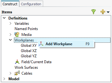
On the model tree, click the icon. From the drop-down list, select Add
Workplane.
Press F9 to use the keyboard
shortcut.
On the Create Workplane dialog, from the drop-down list, select Global YZ.
Use the default workplane label, Workplane1.
Figure 2. The Create Workplane dialog.
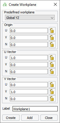
Click Create to create the workplane and to close
the dialog.
The default workplane is used when creating new geometry primitives. For
this example, set the new workplane as the default workplane.
In the model tree, select
Workplane1.
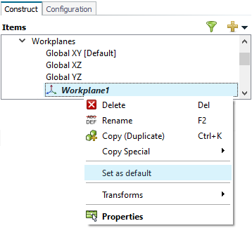
From the right-click context menu, select Set as
default.
Figure 3. The right-click context menu options for
workplanes.
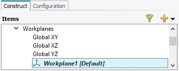
Note: The current default workplane is indicated by the text,
[Default].