The example is intended for users with no or little experience with CADFEKO. It makes use of a completed rectangular horn model to familiarise yourself with model creation in CADFEKO and viewing the simulated results in POSTFEKO.
The example is intended for users with no or little experience with CADFEKO. This example is not an example intended for simulation, but rather to familiarise yourself with model creation in
CADFEKO.
Define a workplane to create an oblique plane. Workplanes simplify the process of creating geometry on oblique planes
in comparison to using transforms.
Add a wire feed to the model. As this example is only for demonstration purposes, this example does not cover the
adding of a port or source to the wire feed.
Create an aperture (hole) in a face or region by using the subtract tool. Create the geometry to be removed and subtract
it from the target part. The target is the part that is reduced by cutting away a section of the part.
Feko is a comprehensive electromagnetic solver with multiple solution methods that is used for electromagnetic field analyses
involving 3D objects of arbitrary shapes.
EDITFEKO is used to construct advanced models (both the geometry and solution requirements) using a high-level scripting language
which includes loops and conditional statements.
One of the key features in Feko is that it includes a broad set of unique and hybridised solution methods. Effective use of Feko features requires an understanding of the available methods.
Feko offers state-of-the-art optimisation engines based on generic algorithm (GA) and other methods, which can be used
to automatically optimise the design and determine the optimum solution.
Feko writes all the results to an ASCII output file .out as well as a binary output file .bof for usage by POSTFEKO. Use the .out file to obtain additional information about the solution.
CADFEKO and POSTFEKO have a powerful, fast, lightweight scripting language integrated into the application allowing you to create
models, get hold of simulation results and model configuration information as well as manipulation of data and automate
repetitive tasks.
The example is intended for users with no or little experience with CADFEKO. This example is not an example intended for simulation, but rather to familiarise yourself with model creation in
CADFEKO.
A model is parametric when it is created using variable expressions. When a variable
expression is modified, any items dependent on that variable are re-evaluated and
automatically updated. It is the recommended construction method when creating a
model, but not compulsory.
Defined variables are stored as part of the model in the .cfx
file.
Open the Create Variable dialog using one of the
following workflows:
On the Construct tab, in the Define group, click the Add Variable icon.
On the model tree, a right-click context menu is available on Variables. From the
list, select Add Variable.
Figure 1. The model tree
(Construction tab).
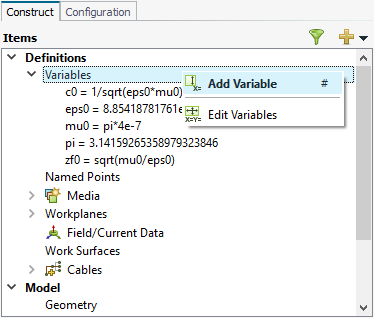
On the model tree, click the icon. From the drop-down list, select Add Variable.
Figure 2. The drop-down list available in the model tree.
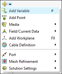
Press # to use the keyboard shortcut.
Create the following variables:
Name
Expression
Comment [Optional]
Width
1
Width of rectangle.
Length
1
Length of rectangle.
BottomDepth
1
Bottom depth of flare.
BottomWidth
1
Bottom width of flare.
FlareLength
1
Length of flare.
TopWidth
2
Top width of flare.
TopDepth
2
Top depth of flare.
Figure 3. The Create Variable dialog.
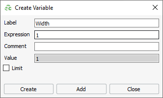
Tip:
Click Add to keep the Create Variable dialog open and add more
variables.
Click Create to add a variable and
close the Create Variable dialog.