Guide Line
Check item for the soldering guide line width and the drawing layers clearance with other geometries or objects.
The Guide Line dialog contains the following
sections:
- Board Direction Definition: To decide the board placement status, use the
soldering mark or define the soldering direction.
- Soldering-Mark Component Group: If the soldering-mark is registered
as components, define it.
- Mark Direction: To define the real soldering direction,
define the mark direction.
Figure 1. Mark Direction Example 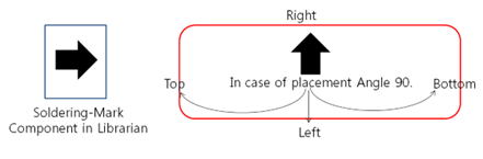
- Mark Direction: To define the real soldering direction,
define the mark direction.
- Soldering Direction: Not using soldering-mark case, define the
direction of the board.
Figure 2. Soldering Direction Example 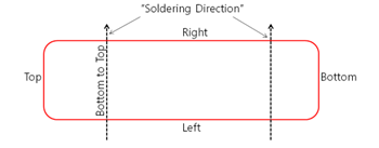
- Soldering-Mark Component Group: If the soldering-mark is registered
as components, define it.
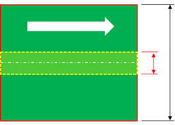
- Guide Line Definition: Define the solder guide line in the PCB with the
drawing object width or height. Additionally, define the direction.
- Guide Line Width (GLW): Using the tools, set the ranges of guide line size, set the guide line specification.
- Guide Line Height (GLH): Using the tools, set the ranges of guide line size, set the guide line specification.
- Guide Line Direction: Set the guide line direction.
- Searching Layer: Set the searching layer where the solder guide line should be placed. Set one of the guideline searching layer.
- Checking: Define the checking rules.
- Clearance: Set the clearance values with components, vias, and
figure holes.
- To Component: Define the checking target components. Check
clearance with components on the same layer or components
with other layers.
- Checking Base: To calculate the clearance between the guide line and component, given guidance will be based on defining the size of components. Component size will be Component Overlapping Checking (COC) area, silk, silk plus pad, and pad region.
- General Clearance: Specify the clearance value for general components.
- Special Component: Specify the clearance value for special components and component group.
- To Via: Set the clearance to via.
- To Hole: Set the clearance to figure hole.
- To Component: Define the checking target components. Check
clearance with components on the same layer or components
with other layers.
- Clearance: Set the clearance values with components, vias, and
figure holes.
- Guide Line Position: Check if the guide line exists in the area that is set
from the board center based on the SMT process direction.
Figure 3. Guide Line Position Example