Power Definitions
Power for transmitters determine the EIRP and can be specified.
Downlink
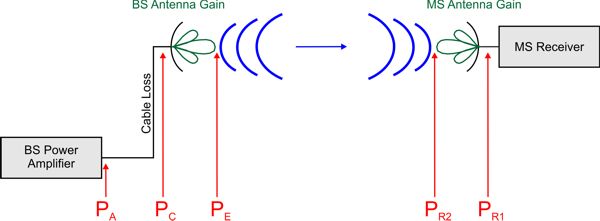
For specification of the Tx power in EIRP or ERP mode, you have to define PE (including cable loss and BS antenna gain). PR1 is the received power including the MS antenna gain.
For the propagation settings (path loss threshold for ray selection) both the BS and the MS antenna gains are not considered.
For example, the path loss is computed as PC - PR2 and includes therefore only the BS antenna gain. Accordingly, the path loss is independent of the selected power mode (OPA, EIRP, ERP) and independent of the defined cable loss.
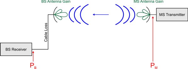
In the network planning results both the BS and MS antenna gain is included, for example, they have the reference to PR1 (maximum received MS power) and PA (minimum required BS transmit power) in the downlink. For the uplink, they have the reference to PB (maximum received BS power) and PM (minimum required MS transmit power).
Uplink