Leaky Feeder Cable
A leaky feeder cable consists of a coaxial cable running along drivages which emits and receives radio waves.
The cable is leaky in that it has gaps or slots in its outer sheath to allow the signal to leak into or out of the cable along its entire length. Because of this leakage of the signal, line amplifiers are required to be inserted at regular intervals, typically every 350 to 500 meters, to boost the signal back up to acceptable levels.
The system has a limited range, and because of the high frequency it uses, transmissions cannot pass through solid rock, which limits the system to a line-of-sight application. It does, however, allow two-way mobile communication.
Creation
Leaky feeder cables can be created using the mouse tool or by importing the coordinates
of the cable from an ASCII file. New cables can be inserted by choosing or by selecting the ![]() icon. Afterward, a dialog opens, where
the type of the new transmitter can be selected.
icon. Afterward, a dialog opens, where
the type of the new transmitter can be selected.
In case the cable is drawn with the mouse, the z-coordinates can be defined right after the mouse tool is closed with the right mouse button. The z-coordinates of all definition points are initialized with the same height, which can be specified in the following dialog. However, all points can also be edited later.
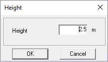
The selected height can be chosen to be an absolute value or to be relative to the contained floor levels or the topography, respectively.
Modification of Parameters
Parameters of leaky feeder cables can be modified by selecting the site to be edited on the Sites tab of the Project dialog or by using the corresponding toolbar icon.
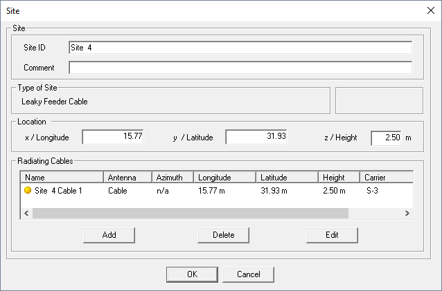
After selecting the cable, the following dialog is displayed:
- Location of Cable
- The coordinates of the cable definition points can be inserted, edited,
inverted, deleted, imported or exported from or to an ASCII file using the
following dialog.
Figure 5. The Coordinates dialog. 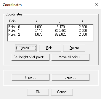
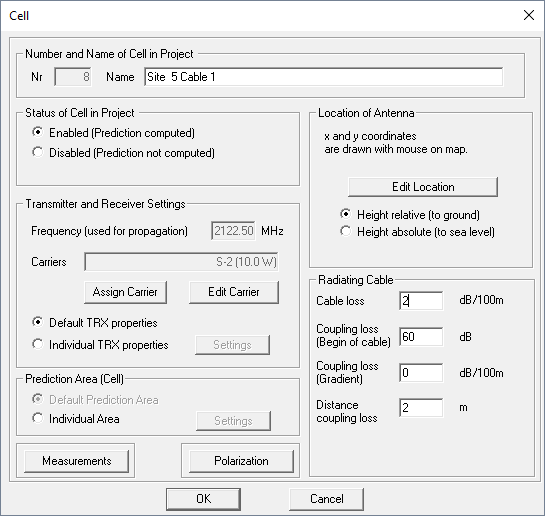
Note: The z-coordinates displayed in this dialog are always absolute coordinates. - Cable Loss [dB/100m]
- The cable loss is based on resistance (Ohm) and frequency dependent losses of a cable. The value must be specified in dB per 100 meters. Reasonable values are between 1 and 30 dB per 100 meters. This parameter is used to determine the loss along the whole cable. Depending on the length of the cable an additional loss will be determined
- Coupling loss (Begin of cable) [dB]
- The coupling loss is the attenuation applied at a specific distance (distance coupling loss) perpendicular to the radiating cable. A coupling loss of 20 dB combined with a distance of 2 meters leads to a path loss value of 20 dB at a distance of 2 meters from the feeding point (source) of the cable.
- Coupling loss (Gradient) [dB/100m]
- The coupling loss can be reduced by defining a (positive) coupling loss gradient. If the coupling loss at the begin of the cable is 10 dB for example and the coupling loss gradient is 2 dB/100m, then the coupling loss at the end of a 100-meter long cable is 8 dB. Along the cable, there is a linear decrease in the coupling loss.
- Distance coupling loss [m]
- This parameter is the distance used to determine the path loss based on the coupling loss. It must always be seen in relation to the coupling loss