Global settings are settings that are not relevant to a specific project or
database.
Click Settings > Global Settings (Directories, Options) to modify the default settings.
These settings are stored in the Windows Registry if ProMan
is closed. If several instances of ProMan are running at the
same time, the global settings of the ProMan instance which
was closed last, are saved to the Windows Registry.
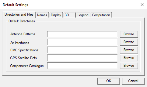
Directories and Files
The Directories and Files tab is used to specify the paths of the
default directories and default selections. Default directory paths are used to find items
(for example, antenna patterns and wireless standards) if they are not available in the
current directory or the directory specified in the current project.Figure 1. The Default Settings dialog - Directories and
Files tab.
Default directories are specified for the following:
Antenna Patterns
Air Interfaces
EMC Specifications
GPS Satellite Defs
Components Catalogue
Names
The Names tab is used to specify the default descriptions used for
new objects placed in the scenario. Descriptions can be changed afterwards. You can specify
the default descriptions of the following items:
Sites
Antennas / Cells
LMUs
Figure 2. The Default Settings dialog - Names
tab.
Display
The Display tab is used to specify the default settings for screen
visualization.
Figure 3. The Default Settings dialog - Display
tab.
Filter results when displayed
Results are filtered with a median filter when they are displayed on the screen.
This option does not affect the result files on the hard disk in contrast to
Filter results when computed.
Use auto scale for results when initially displayed
The legend is scaled automatically if a result is loaded from the hard disk.
Path loss values with positive sign (instead of negative)
Path loss values are shown with a positive sign instead of a negative sign.
Extend file names after mathematical operation with files (e.g. add)
File names of results are extended with the name of a mathematical operation, for
example, diff is added to the file name if a differential operation was
done.
For continuous scale: Use colors of max (min) value for all values beyond max
(min)
The colors for minimum / maximum values are used for all result values below / above
the thresholds. If this option is unselected, result values below / above the minimum
/ maximum value are not displayed on the screen.
Draw also unpredicted pixels
Unpredicted pixels are drawn with white colored. Otherwise, they are
transparent.
Load rays also for unpredicted pixels (if available)
Rays are also loaded from hard disk for not computed pixels if they are
available.
Show link to site/cell in cell area and site area maps
Shows a link to the site / cell for the network planning results cell area and site
area maps.
Draw pixel center
Displays the pixel center in the 2D view.
Draw pixel grid
Displays the pixel grid in the 2D view.
3D
The 3D tab is used to specify the default settings for the 3D
view.
Figure 4. The Default Settings dialog - 3D
tab.
3D Display Settings
Light coming from north: Locations are on the southern hemisphere. Disable view for
topo / clutter databases with more than X mega pixels: To limit the memory usage, the
3D view can be disabled for very large files.
Prediction on surfaces and non-horizontal planes
As predictions on surfaces of walls cannot be shown in the 2D view, there is a
message box available to remind you to launch the 3D view to see the computed results
on the screen.
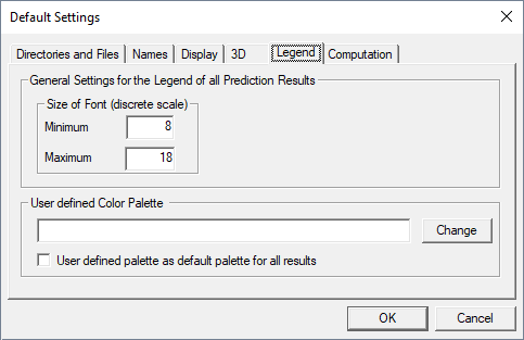
Legend
The Legend tab is used to specify the default settings for the
legend.
Figure 5. The Default Settings dialog - Legend
tab.
Size of font (discrete scale)
A minimum and maximum font size can be defined for the discrete scale. In case of
the continuous scale, an automatic scaling of the font size is done.
User defined color palette
A user-defined color palette can be specified. If the option User defined
palette as default for all results check box is selected, the specified
palette is automatically applied to all results. As long as this option is enabled, it
is not possible to select a color palette in the local settings.
Computation
The Computation tab is used to specify the default settings for
computations.
Figure 6. The Default Settings dialog - Computation
tab.
Ask before former results are overwritten during re-computation of project
If this option is enabled, you will be asked if available prediction results can be
overwritten during re-computation.
Generate log file during computations (saved in result directory)
A log file is generated during predictions. The file contains all the lines which are
displayed during predictions on the screen.
Save prediction results additionally in customer defined file format
If a customer file format is available in your version of WinProp, the results are additionally stored in this format.
Save prediction result of each antenna/cell in individual sub-directory
Results of each antenna are stored in an individual sub directories.
Filter propagation results when computed
Prediction results are filtered after prediction. This affects accuracy. In contrast
to Filter results when displayed this item does lead to
modifications of the results on the hard disk.
Limit dynamic in antenna pattern
(Base station)
The dynamic range in antenna patterns at base stations can be limited to a
user-defined dynamic range.
(Mobile station)
The dynamic in antenna patterns at mobile stations can be limited to a
user-defined dynamic range. Currently, this option affects point-to-point
predictions only.
This option can be used to avoid deep notches in the antenna pattern. The value
defined by you describes the threshold for the maximum attenuation with respect to
the maximum gain.
For example, if the maximum gain of the antenna is 10 dBi and the gain in a certain
direction is -5 dBi, then normally this gain is applied. But if the dynamic range
feature is set to 8 dB, the effective gain in the aforesaid direction is 10 dBi
(maximum gain) – 8 dB (dynamic range) = 2 dBi and not -5 dBi. This means the gain
values cannot be smaller than the maximum gain minus the dynamic range value, for
example, if the dynamic range value is set to 0 dB the result is isotropic
radiation.
Note: A user-defined dynamic range affects the accuracy of results.
Individual indoor results for each CNP building
Indoor results of CNP buildings1 can be stored in
separate result files (optional).
Number of concurrent computations
In case of multi-core / multi CPU machines, the maximum number of parallel
computations can be specified. By default, this parameter is set to the number of
available cores / CPUs.
1 Buildings, which have been modeled as indoor
databases and imported to the urban environment database.