SS-T: 2040 Joints
Create joints in SimSolid.
- Purpose
- SimSolid performs meshless structural
analysis that works on full featured parts and assemblies, is tolerant of
geometric imperfections, and runs in seconds to minutes. In this tutorial,
you will do the following:
- Learn how to create joints - hinge and virtual pins.
- Model Description
- The following model file is needed for this tutorial:
- Joints.ssp
-
Figure 1. 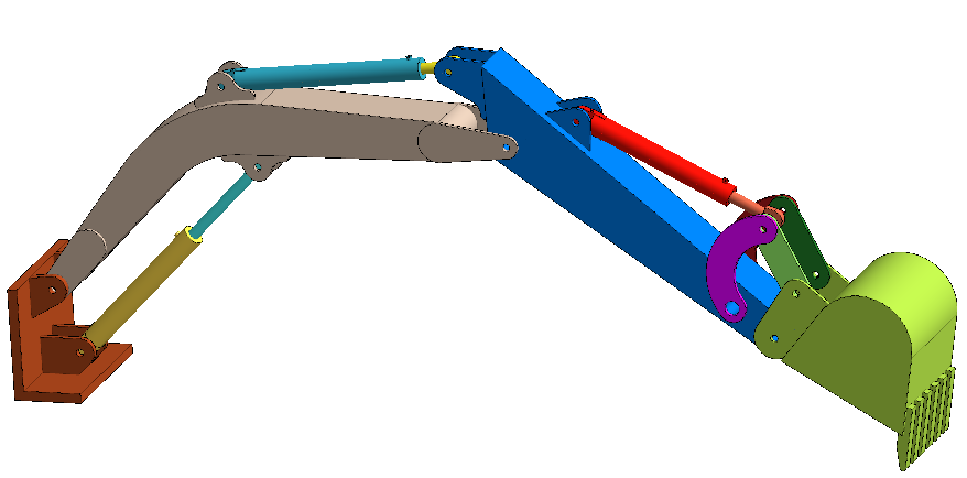
Open Project
- Start a new SimSolid session.
-
On the main window toolbar, click Open Project
 .
.
- In the Open project file dialog, choose Joints.ssp
- Click OK.
Create Hinge Joints
-
On the Connections workbench, select
 > Joints.
- In the dialog, select the Hinge radio button.
-
In the modeling window, select the faces as shown in
orange in Figure 2.
Figure 2. 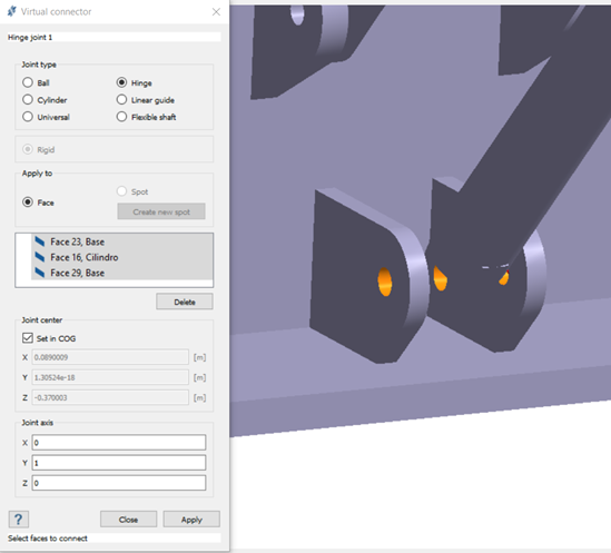 Joint center and axis are automatically picked based on selected faces. The values can be edited if needed.
 - Click Apply.
-
Repeat steps 1
through 4 to
create hinge joints at the locations shown in Figure 3.
Figure 3. 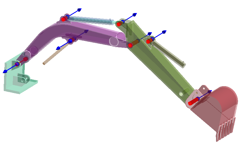
Create Sliding Contact
-
On the Connections workbench, select
 (Add/edit part connections).
- Click the Primary connect tab.
- For the primary part, select part6. For the secondary part, select Cilindro.
- Accept default gap and penetration tolerances.
- For Resolution, select Normal.
-
Click Find connections.
One cylindrical connection between the two parts should be created.
- Click OK.
-
Repeat steps 1
through 7 to
create connections with the other hydraulic part pairs.
- part 2 (primary), Cilindro (secondary)
- part 3 (primary), Cilindro (secondary)
- In the Project Tree, hold down Control + select all regular connections.
- Click Edit default contact condition.
- Change the default contact condition to Sliding without friction for all cylinder connections.
-
Click OK.
The proper sliding connections between hydraulic cylinders are shown in Figure 4.
Figure 4. 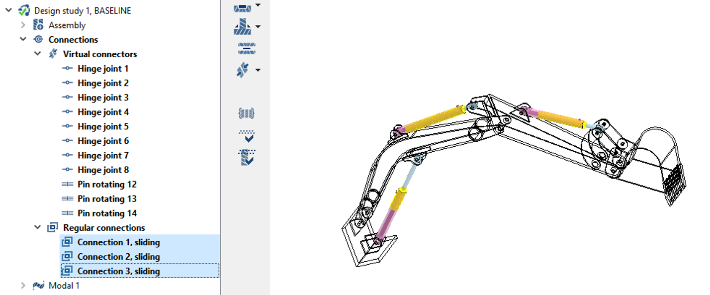
Create Virtual Pin
-
On the Connections workbench, select > Pin.
- In the dialog, verify the Rotating radio button is selected.
-
In the In the modeling window, select the faces as
shown in orange in Figure 5.
Figure 5. 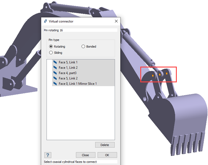
- Click Apply.
-
Repeat steps 1
through 4 to
create virtual pins at the locations shown in Figure 6.
Figure 6. 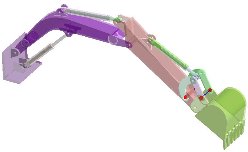
Note: The differences between a hinge joint and a virtual pin are as follows:- Hinge joints allow only rotation about the said axis whereas pins can be rotating/bonded/sliding.
- Virtual pins are used to only connect cylindrical faces whereas hinge joint doesn’t have a restriction on the type of face.
- Virtual pins can connect more than two parts whereas Joints are limited to two parts.
Review Connections
-
On the Connections workbench, click
 (Find and show disconnected groups of parts).
Figure 7. 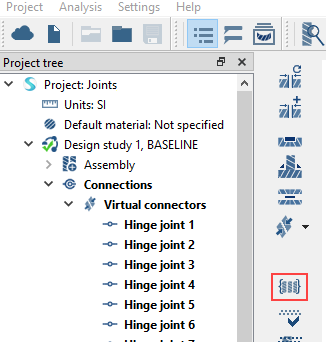
A message appears stating that the model has no disconnected groups of parts. - Click OK.
Run Analysis
- On the Project Tree, open the Analysis Workbench.
-
Click
 (Solve).
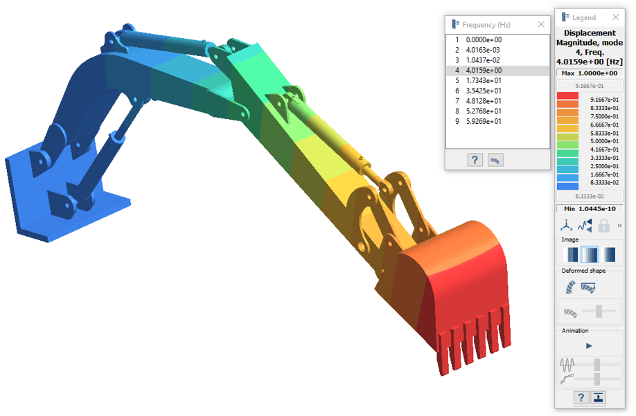
Review Results
- During the analysis, when the warning message appears, click Yes.
-
On the Analysis Workbench
toolbar, click
 (Results plot).
-
Select Displacement Magnitude.
The Legend window opens and displays the contour plot. The Frequency (Hz) window opens and displays the modes.
Figure 8.