SS-T: 2050 Remote Mass
Create Remote Mass in SimSolid.
- Purpose
- SimSolid performs meshless structural
analysis that works on full featured parts and assemblies, is tolerant of
geometric imperfections, and runs in seconds to minutes. In this tutorial,
you will do the following:
- Create Remote Mass on a Gantry hoist.
- Model Description
- The following file is needed for this tutorial:
- RemoteMass.ssp
-
Figure 1. 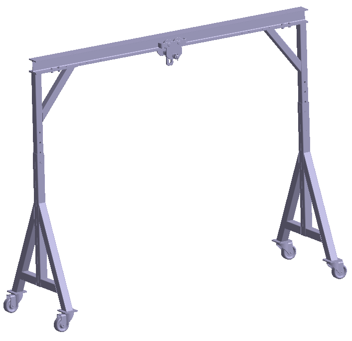
Open Project
- Start a new SimSolid session.
-
On the main window toolbar, click Open Project
 .
.
- In the Open project file dialog, choose RemoteMass.ssp
- Click OK.
Create Remote Mass
-
On the Connections workbench, select
 > Remote Mass.
-
In the modeling window, select the faces as shown in
orange in Figure 2.
Figure 2. 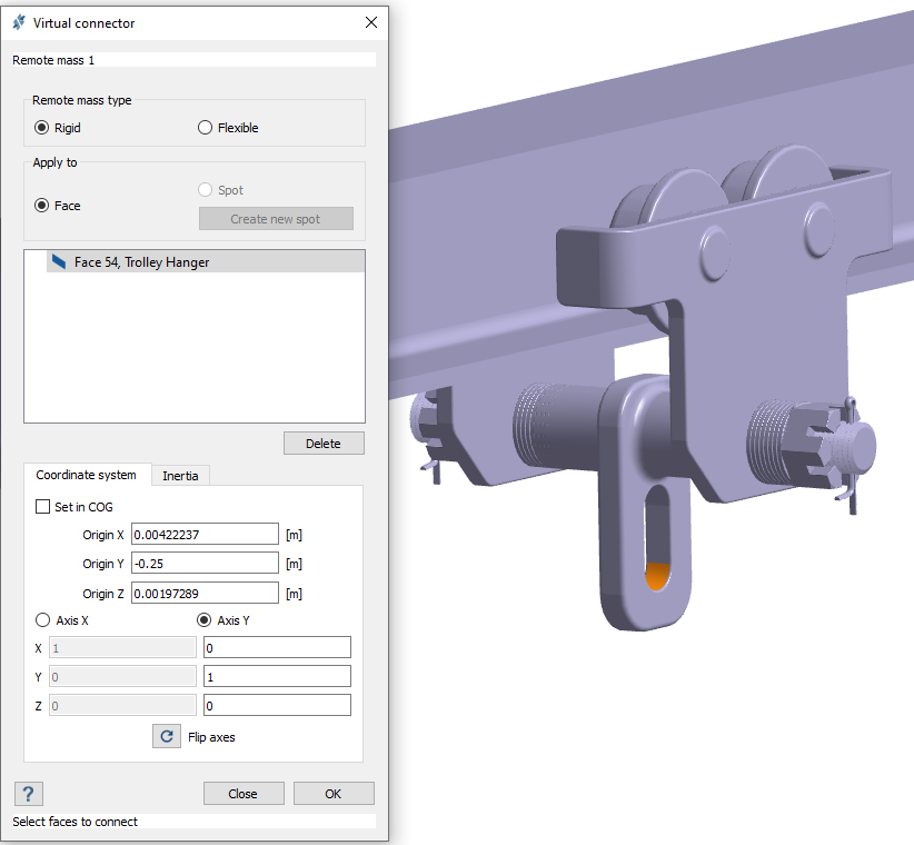
- Verify the Coordinate system tab is selected and uncheck Set in COG.
-
Enter coordinates for where to apply the remote mass.
- For Origin X, enter 0.00422237.
- For Origin Y, enter -0.25.
- For Origin Z, enter 0.00197289.
-
Set the Coordinate system.
- Select the Axis X radio button and enter [1, 0, 0] for [X, Y, Z].
- Select the Axis Y radio button and enter [0,1, 0] for [X, Y, Z].
- Click on the Inertia tab.
-
For Mass, enter 25.
Figure 3. 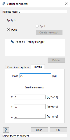
-
Click OK.
The Remote Mass is listed under Connections > Virtual Connectors in the Project Tree. It is shown in the modeling window as a point mass at the specified coordinates.
Figure 4. 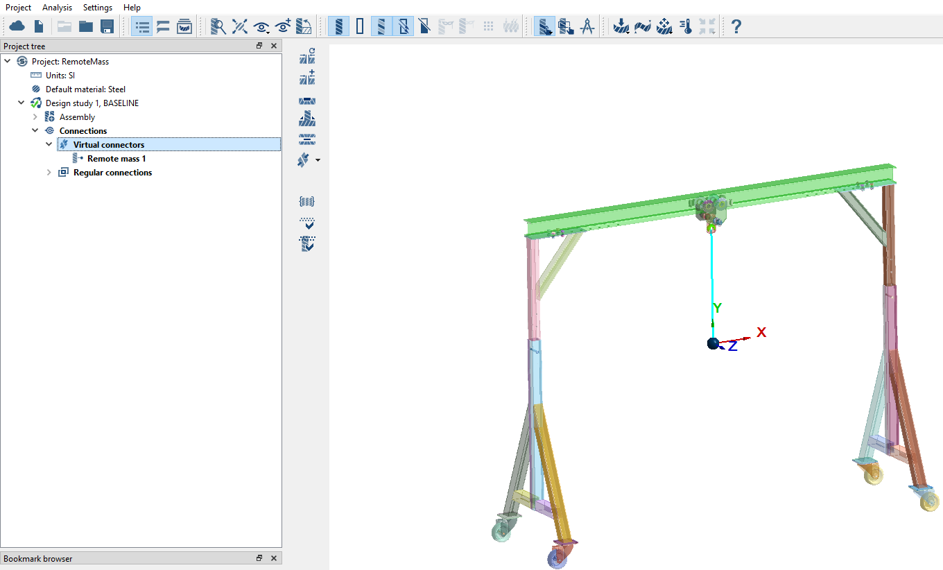
Create Modal Analysis
-
On the main window toolbar, click the
 (Modal analysis) icon.
- In the popup Number of modes window, specify the number of modes as 9.
-
Click OK.
The new modal analysis appears in the Project Tree.
Create Immovable Supports
-
In the Analysis Workbench, click Immovable
Support
 .
.
- In the dialog, verify the Faces radio button is selected.
-
In the modeling window, select the faces of the tires
as shown in Figure 5.
Figure 5. supports_faces.png)
- Click OK.
Edit Solution Settings
- In the Analysis branch of the Project Tree, double-click on Solution settings.
- In the Solution settings dialog, for Adaptation select Global+Local in the drop-down menu.
- Click OK.
Run Analysis
- On the Project Tree, open the Analysis Workbench.
-
Click
 (Solve).
Review Results
-
On the Analysis Workbench
toolbar, click
 (Results plot).
-
Select Displacement Magnitude.
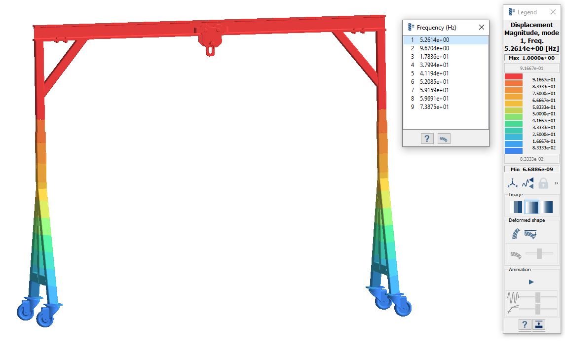
The Legend window opens and displays the contour plot. The Frequency (Hz) window opens and displays the modes. You can cycle between the frequencies to view their mode shapes.
Figure 6. 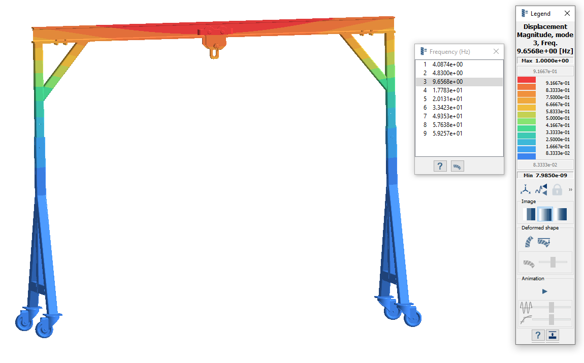
Compare Results With and Without Remote Mass
-
Copy Design Study 1 to create Design Study 2.
- In the Project Tree, right-click on Design Study 1, and then select Copy from the context menu.
- Under , right-click on Remote mass 1, and then select Delete from the context menu.
-
Select Design Study 2 and click
 (Solve) on the workbench toolbar.
-
Plot Displacement Magnitude for Design Study 2.
-
On the Analysis Workbench
toolbar, click (Results plot).
- Select Displacement Magnitude.
-
On the Analysis Workbench
toolbar, click
-
In the Project Tree, click between the
Results branches for both Modal analyses to compare
the Displacement Magnitude plots.
Figure 7. Results with Remote Mass
Figure 8. Results without Remote Mass