SS-T: 2010 Adhesives
Create Adhesives in SimSolid.
- Purpose
- SimSolid performs meshless structural
analysis that works on full featured parts and assemblies, is tolerant of
geometric imperfections, and runs in seconds to minutes. In this tutorial,
you will do the following:
- Learn how to create Adhesives for an entire connection area.
- Learn how to create Adhesives for a local area by adding adhesives to tubular parts.
- Model Description
- The following files are needed for this tutorial:
- Rearview mirror.x_b
- Rearview mirror_AdhesiveSolids.x_b
-
Figure 1. 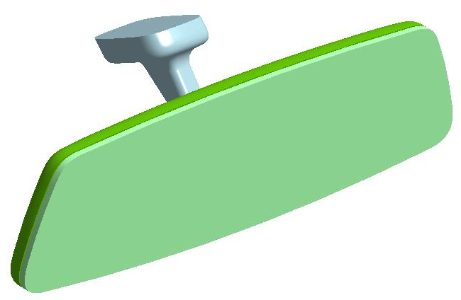
Import Geometry
- Open a new SimSolid session.
-
Click Import from file
 .
.
- In the Open geometry files dialog, choose Rearview mirror.x_b.
-
Click Open.
The assembly will load in the modeling window. The Automatic connections dialog opens.
Create Connections
- In the Automatic connections dialog, specify the Gap and Penetration tolerances as 1.1.
- Set Connection resolution level to Normal.
-
Click OK.
Note:
- SimSolid creates connections even in areas with overlapping geometry.
- SimSolid automatically identifies bolts, nuts and washers.
- Sliding contact is applied automatically in bolt shanks, bonded is applied otherwise.
Apply Adhesive to Connection Area
- In the Project Tree, expand .
-
Right-click on Connection 1 and select Apply
adhesive
 from the context menu.
- In the Apply material dialog, ensure the Material database radio button is selected.
- In the dialog, expand the Generic materials folder and select Adhesive or any available material from the database.
-
Click Apply to selected connections.
In the Project Tree, Connection 1 is Replaced with Adhesive 1. A new Adhesive folder is created.
Figure 2. 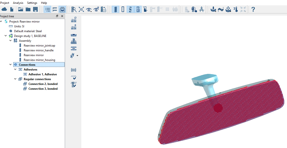
-
Click
 to close the project.
Import Geometry
-
Click the (Import from file).
- In the Open geometry files dialog, hold down Control and multi-select Rearview mirror.x_b and Rearview mirror_AdhesiveSolids.x_b.
-
Click Open.
The Automatic connections dialog opens.
- Use default gap and penetration tolerances to create automatic connections.
- Click OK.
-
When the disconnected groups warning appears, click OK and Close to
dismiss.
Figure 3. 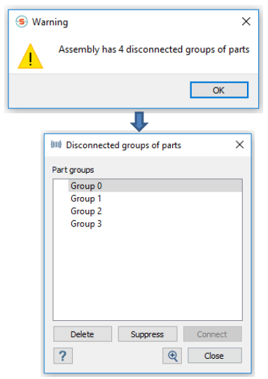
Create Adhesives
-
On the Connections workbench toolbar, click
 (Create adhesive
connections from solids).
(Create adhesive
connections from solids).
- In the Create adhesive connections dialog, for Adhesive width enter 10 mm.
-
In the Project Tree, under Assembly, select the two
cylinders.
Tip: The cylinders can also be selected in the modeling window.
-
In the Create adhesive connections dialog, click
Find connections.
Found Adhesives appear in the dialog under Connections.
- Click Select to apply material to found adhesives.
- In the Apply material dialog, ensure the Material database radio button is selected.
- In the Apply material dialog, expand the Generic materials folder and select Adhesives or any available material from the database.
-
Click Apply adhesive material.
Tip: To edit Adhesives, right-click on an Adhesives and select Edit adhesive.
- Click OK.
Review Connections
-
On the Connections workbench, click
 (Find and show disconnected groups of
parts).
A message appears stating that the model has no disconnected groups of parts.
(Find and show disconnected groups of
parts).
A message appears stating that the model has no disconnected groups of parts.Figure 4. 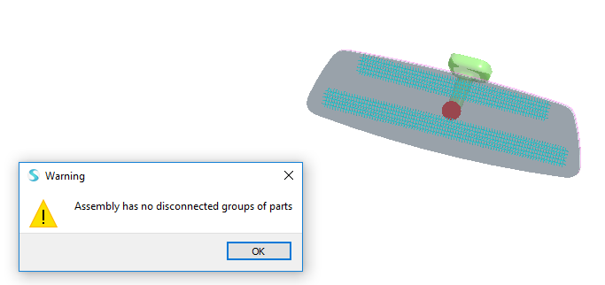
- Click OK.