SS-V: 9000 Wave Propagation in a Waveguide
Test No. VE01Propagation of the fundamental mode wave in a waveguide at different frequencies
Definition
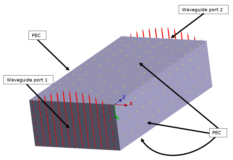
- 10 mm x 20 mm x 40 mm
- Side walls are at the PEC (Perfect Electric Conductor) conditions and ports are at the end faces
- Results are presented for Port 1 active, Port 2 passive
- Properties
- Value
- Relative permittivity
- 1.0
- Relative permeability
- 1.0
Results

| Reference | SimSolid | % Difference | |
|---|---|---|---|
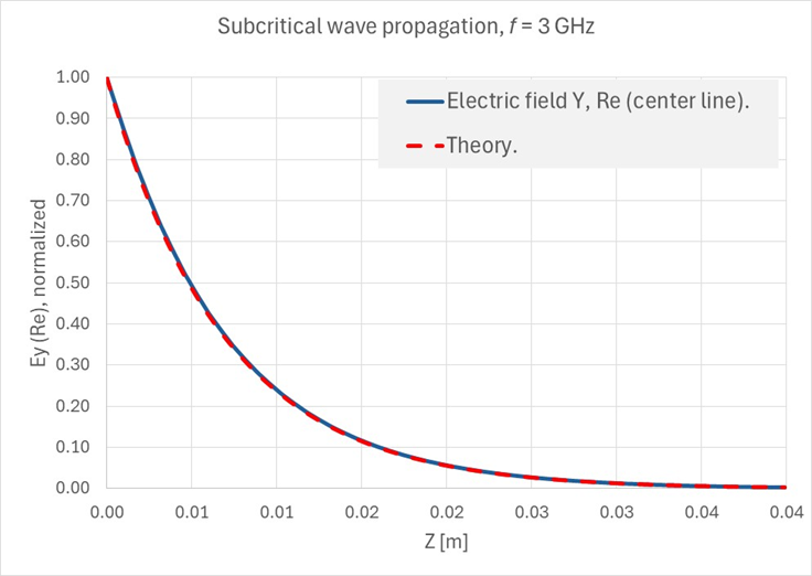
| Decrement rate [m-1] | 143.947 | 143.87 | 0.05% |

| Reference | SimSolid | % Difference | |
|---|---|---|---|
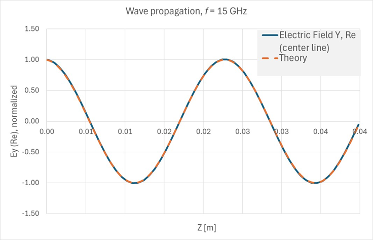
| Wave number [m-1] | 272.32 | 272.49 | 0.06% |
1 Pozar, D.M., Microwave engineering,
4th Edition, John Wiley & Sons, Inc., 2012, 3.3.
2 Jianming, J., The finite element method
in electromagnetics, 3rd Edition, John Wiley & Sons, Inc., 2014,
11.1.2.