Antenna
![]()
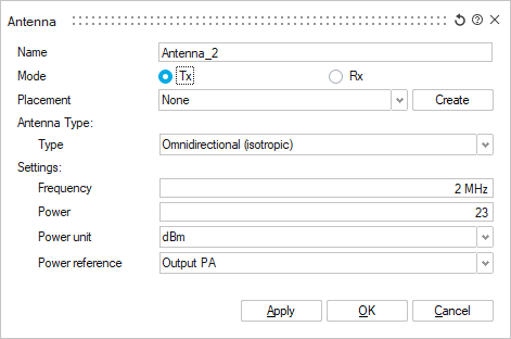
The Antenna dialog provides options to define and place an equivalent antenna in the model.
Mode
Select if the antenna is a transmitting (Tx) antenna or a receiving antenna (Rx). When no receiving antenna pattern is specified, the received-power plots in the areas of interest are based on a hypothetical isotropic (omni-directional) receiver antenna, and only the transmitter antenna is specified. This is sufficient for some mobile-communication scenarios in which the base stations have directional antennas while the hand-held mobile stations have very broad antenna patterns and may be held in any orientation.
Placement
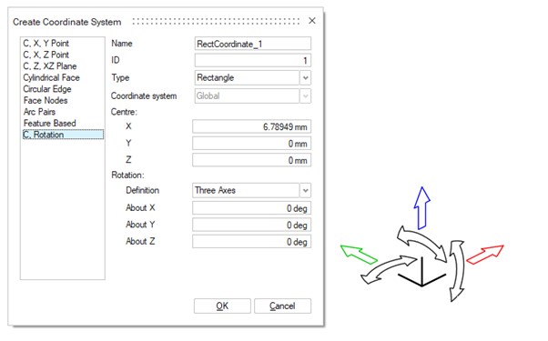
Select a predefined coordinate system from the solution using the drop-down list.
- Use the dialog input fixed coordinates (X, Y, and Z) for the centre of the antenna and define the rotation.
- Use the arrows on the Move tool in the 3D view to move (drag, rotate) the placement freely.
- Click on the origin of the Move tool in the 3D view and drag or snap to geometry.
Once done, click the X to close the Move tool dialog. Click OK to close the Create Coordinate System dialog.
Antenna Type
Specify the antenna type (Directional or Omnidirectional). Directional transmitters are used for cellular networks and point-to-point wireless links.
If a directional antenna is selected (instead of isotropic/omnidirectional), a 3D antenna pattern file must be selected. Use the Import button to select a file of type (.apb, .apa, .msi, .pln, .ffe). The selected file will be imported into the database and saved as an input file in the database folder.
Settings
- Output power of the PA (power amplifier)
- ERP (equivalent radiated power, for example, relative to dipole antenna)
- EIRP (equivalent isotropic radiated power, for example, relative to
isotropic antenna).
If G is the gain of the antenna (in dBi), the values can be determined via the following equation: