/MAT/LAW81
Block Format Keyword This law is based on Drucker-Prager yield criteria with cap. It has a strain-hardening cap model based on the principles of Foster. Plasticity has an isotropic hardening.
Format
| (1) | (2) | (3) | (4) | (5) | (6) | (7) | (8) | (9) | (10) |
|---|---|---|---|---|---|---|---|---|---|
| /MAT/LAW81/mat_ID/unit_ID | |||||||||
| mat_title | |||||||||
| K0 | G0 | c0 | Pb0 | ||||||
| Eps_max | |||||||||
| fct_IDK | fct_IDG | fct_IDC | fct_IDPb | Isoft | |||||
| Kw | n0 | S0 | U0 | ||||||
| Tol | |||||||||
Definition
| Field | Contents | SI Unit Example |
|---|---|---|
| mat_ID | Material
identifier. (Integer, maximum 10 digits) |
|
| unit_ID | Unit Identifier. (Integer, maximum 10 digits) |
|
| mat_title | Material
title. (Character, maximum 100 characters) |
|
| Initial
density. (Real) |
||
| K0 | Initial bulk
modulus. (Real) |
|
| G0 | Initial shear
modulus. (Real) |
|
| c0 | Initial material
cohesion. (Real) |
|
| Pb0 | Initial cap limit
pressure. (Real) |
|
| Friction
angle. (Real) |
||
| Plastic flow
angle. (Real) |
||
| Ratio of:
Default = 0.5 (Real) |
||
| Eps_max | Maximum dilatancy
(negative number limiting
). Default = -1020 (Real) |
|
| Initial value of the
plastic volumetric strain. 3 (Real) |
||
| fct_IDK | (Optional) Function
identifier for the bulk modulus scale factor versus the plastic
volumetric strain. 4 (Integer) |
|
| fct_IDG | (Optional) Function
identifier for the shear modulus scale factor versus the plastic
volumetric strain. (Integer) |
|
| fct_IDC | (Optional) Function
identifier for the material cohesion scale factor versus the
equivalent plastic strain. (Integer) |
|
| fct_IDPb | (Optional) Function
identifier for the cap limit pressure scale factor versus the
plastic volumetric strain. (Integer) |
|
| Isoft | Cap softening flag.
(Integer) |
|
| Kw | Pore bulk modulus
(water). (Real) |
|
| n0 | Initial
porosity. (Real) |
|
| S0 | Initial
saturation. (Real) |
|
| U0 | Initial pore
pressure. (Real) |
|
| Tol | Tolerance for cap shift
viscosity. Default = 1.0E-4 (Real) |
|
| Viscosity
factor. Default = 0.5 (Real) |
Example
#RADIOSS STARTER
#---1----|----2----|----3----|----4----|----5----|----6----|----7----|----8----|----9----|---10----|
/UNIT/1
unit for mat
                  kg                   m                   s
#---1----|----2----|----3----|----4----|----5----|----6----|----7----|----8----|----9----|---10----|
#-  2. MATERIALS:
#---1----|----2----|----3----|----4----|----5----|----6----|----7----|----8----|----9----|---10----|
/MAT/LAW81/1/1
LAW81
#              RHO_I
                1700
#                 K0                  G0                  c0                 PB0
              2.83E9              1.31E9                   1                   1
#                PHI                 PSI
                  15                  10
#              ALPHA           EPS_p_max               EPS_0
                  .5                 .02                .002
#  Fct_IDK   Fct_IDG   Fct_IDc  Fct_IDPb    I_soft
         0         0         3         4         1
#                 Kw                  n0                  S0                  U0
              2.5E10                 0.1                0.99                 0.0
#                Tol             alpha_v
              0.0001                 0.5
#---1----|----2----|----3----|----4----|----5----|----6----|----7----|----8----|----9----|---10----|
#-  3. FUNCTIONS:
#---1----|----2----|----3----|----4----|----5----|----6----|----7----|----8----|----9----|---10----|
/FUNCT/3
Yield Hardening
#                  X                   Y
                   0                2000
                  .1             2002000
                   1             2002000
#---1----|----2----|----3----|----4----|----5----|----6----|----7----|----8----|----9----|---10----|
/FUNCT/4
Cap Hardening
#                  X                   Y
                  -1                1000
                   0                1000
                .001               30000
               .0022               70000
               .0024               80000
                .004              100000
               .0056              200000
               .0078              800000
#---1----|----2----|----3----|----4----|----5----|----6----|----7----|----8----|----9----|---10----|
#ENDDATA
/END
#---1----|----2----|----3----|----4----|----5----|----6----|----7----|----8----|----9----|---10----|
Comments
- The yield surface is defined
as:
(1) Where,
if
if
Where,- p
- Pressure
- q
- von Mises stress
- c
- Material cohesion
- P0
- Pressure, where
- pb
- Cap limit pressure
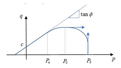
Figure 1.In this material, yield surface and failure surface are the same.
- Plastic flow is governed by the
non-associated flow potential G, as:
if
if
if , the flow becomes associated on the cap.
- If cap softening is allowed, can decrease, therefore it is recommended to define the following curves on a relevant range. For example, if , negative values.
- The initial values for bulk
modulus, shear modulus, material cohesion, and cap limit pressure can be scaled
by defining a function as the scale factor curve for each respective value. If
the function is not defined, then the value is considered constant. For
example:
If fct_IDK = 0 then,
If fct_IDK ≠ 0 then, , with the function defined in fct_IDK
- The initial bulk modulus and shear
modulus can be calculated as:
;
With,- Poisson’s ratio
- Young’s modulus of concrete
- The porosity is defined so that
it represents the volume fraction of voids, with respect to the total material
volume.
(2) In the elastic case, the void volume does not change. However, in the plastic case, the porosity change is defined by:(3) - Effect of pores filled with
water: The initial state of the pores is defined by the initial porosity, initial saturation, and initial pore pressure n0, U0 and S0 which can be calculated as:
(4) If the then the entered value for S0 is not used and instead S0 is recalculated.
- The following user variables are
available for post-treatment:
USR1 is the equivalent plastic strain EPSPD
USR2 is the plastic volumetric strain EPSPV
USR3 is the cohesion c
USR4 is the cap limit pressure Pb
USR5 pore pressure U
USR6 porosity n
USR7 saturation S
USR8 cap shift