/INTER/TYPE24

Block Format Keyword TYPE24 is a general nodes-to-surface contact interface using the penalty method.

Penalty stiffness is constant and therefore, the time step is not affected (for standard penalty stiffness). Solid elements are given a zero gap. Three types of inputs contacts can be defined: single surface, surface to surface, or nodes to surface. This contact interface can replace interface TYPE3, TYPE5, or TYPE7. For implicit solution, this interface TYPE24 is only available with SMP.

Format

(1) (2) (3) (4) (5) (6) (7) (8) (9) (10)
/INTER/TYPE24/inter_ID/unit_ID
inter_title
surf_ID1 surf_ID2 Istf Irem_i2 Idel Ipstif
grnd_IDs Iedge Edge_angle Gap_max_s Gap_max_m
Stmin Stmax Igap0 Ipen0 Ipen_max Stfacm
Required Fields
(1) (2) (3) (4) (5) (6) (7) (8) (9) (10)
Stfac Fric Tstart Tstop
IBC Inacti VISs Tpressfit
Ifric Ifiltr Xfreq sens_ID Dtstif fric_ID
Read this input only if Ifric > 0
(1) (2) (3) (4) (5) (6) (7) (8) (9) (10)
C1 C2 C3 C4 C5
Read this input only if Ifric > 1
(1) (2) (3) (4) (5) (6) (7) (8) (9) (10)
C6

Definition

Field Contents SI Unit Example
inter_ID Interface identifier.

(Integer, maximum 10 digits)

unit_ID Unit identifier.

(Integer, maximum 10 digits)

inter_title Interface title.

(Character, maximum 100 characters)

surf_ID1 First surface identifier. 1

(Integer)

surf_ID2 Second surface identifier.

(Integer)

Istf Interface stiffness definition flag (used only when Istf > 1 and Istf < 7) . 2 3
= 0
Set to the value defined in /DEFAULT/INTER/TYPE24.
= 2
Interface stiffness is the average of the main and secondary stiffness.
= 3
Interface stiffness is the maximum of the main and secondary stiffness.
= 4
Interface stiffness is the minimum of the main and secondary stiffness.
= 5
Interface stiffness is the main and secondary stiffness in series.
= 6
Interface stiffness is the minimum of the main and secondary stiffness with special adjustment to improve convergence for implicit solutions.
=7
Interface stiffness is only based on stability condition. 13
= 12
Nitsche method is used with the average of the main and secondary stiffness.
= 13
Nitsche method is used with the maximum of the main and secondary stiffness.
= 14
Nitsche method is used with the minimum of the main and secondary stiffness.
= 1000 Default, if /DEFAULT/INTER/TYPE24 is not defined.
Interface stiffness is only based on the main side stiffness.

(Integer)

Irem_i2 Deactivating flag for the secondary node, if the same contact pair (node/segment) has been defined in interface TYPE2.
=0
Set to the value defined in /DEFAULT/INTER/TYPE24.
=1 Default, if /DEFAULT/INTER/TYPE24 is not defined
Secondary nodes in /INTER/TYPE2 tied contacts are removed from this contact.
=3
No change to secondary nodes.
Idel Node and segment deletion flag.
= 0
Set to the value defined in /DEFAULT/INTER/TYPE24.
= 1
When all the elements (4-node shells, 3-node shells, solids) associated to one segment are deleted, the segment is removed from the main side of the interface. It is also removed in case of explicit deletion using Radioss Engine keyword /DEL in the Engine file.
Additionally, non-connected nodes are removed from the secondary side of the interface.
= 2
When a 4-node shell, a 3-node shell or a solid element is deleted, the corresponding segment is removed from the main side of the interface. It is also removed in case of explicit deletion using Radioss Engine keyword /DEL in the Engine file.
Additionally, non-connected nodes are removed from the secondary side of the interface.
= 1000 Default, if /DEFAULT/INTER/TYPE24 is not defined.
No deletion.
Note: Using Idel results in higher CPU cost.
Ipstif Add contact stiffness flag based on stability condition: 13
= 0 (Default)
No additional stiffness based on stability condition.
= 1 (Default when using Istf=7)
Additional stiffness based on stability condition is used with the masses coming from the mesh (density, element size) only.
= 2
Additional stiffness based on stability condition is used with the initial masses (density, element size, added mass, mass scaling).

(Integer)

grnd_IDs Nodes group identifier. 1

If defined, node group will be added as secondary nodes.

(Integer)

Iedge Edge to edge contact flag.
= 0 (Default)
Set to the value defined in /DEFAULT/INTER/TYPE24.
= 1
Edge to edge contact is activated using the external border edges from surf_ID1 and surf_ID2 and sharp edges between contact segments. 9
= 1000 Default if /DEFAULT/INTER/TYPE24 is not defined
No edge to edge contact.

(Integer)

Edge_angle Edge angle.

Only used if Iedge =1. Sharp edges are included in edge contact if the angle between two segments which share the same edge is smaller than Edge_angle value. 9

Default = 135° (Real)

[ deg ]
Gap_max_s Secondary maximum gaps. 4

Default = 1030 (Real)

[ m ]
Gap_max_m Main maximum gaps. 4

Default = 1030 (Real)

[ m ]
Stmin Minimum stiffness (used only when Istf > 1 and Istf < 7). 2

(Real)

[ N m ]
Stmax Maximum stiffness (used only when Istf > 1 and Istf < 7). 2

Default = 1030 (Real)

[ N m ]
Igap0 Gap modification flag for secondary shell nodes on the free edges.
= 0 (Default)
Set to the value defined in /DEFAULT/INTER/TYPE24.
= 1
Set gap to zero for the secondary shell nodes.
= 1000 Default if /DEFAULT/INTER/TYPE24 is not defined
No change.

(Integer)

Ipen0 Initial penetration detection flag. 8
= 0 (Default)
Set to the value defined in /DEFAULT/INTER/TYPE24.
= 1
Including self-impact in each part.
= 1000 Default, if /DEFAULT/INTER/TYPE24 is not defined
Excluding self-impact in each part.

(Integer)

Ipen_max Maximum initial penetration. 7

Default = 0 (Real)

[ m ]
Stfacm Scale factor for stiffness based on stability condition (Ipstif > 0 or Istf =7). 13
= 0.1 (Default)
Standard interface stiffness only using Istf.

(Real)

Stfac Interface stiffness scale factor. 2

Default = 1.0 (Real)

Fric Coulomb friction. 5

(Real)

Tstart Start time. 9

(Real)

[ s ]
Tstop Temporary deactivation time. 9

Default = 1030 (Real)

[ s ]
IBC Deactivation flag of boundary conditions at impact.

(Boolean)

Inacti Initial penetration flag. 7
= -2
All initial penetrations are taken into account and the stiffness to remove intersections is based on Istf = 2 and Stfac.
= -1
All initial penetrations are taken into account and the stiffness to remove intersections is based on Istf = 4 and Stfac.
= 0 (Default)
Set to the value defined in /DEFAULT/INTER/TYPE24.
= 5
The main segment is shifted by the initial penetration value P 0 .
If P P 0 , then P ' = P P 0 , where P 0 is the initial penetration.
= 1000 Default, if /DEFAULT/INTER/TYPE24 is not defined
Only tiny initial penetrations will be taken into account.

(Integer)

VISs Critical damping coefficient on interface stiffness.

Default = 0.05 (Real)

Tpressfit Time duration to apply contact forces due to initial penetrations (press-fit). Used only with Inacti=-1 explicit solution only. 7

Default = time corresponding to 10000 cycles (Real)

[ s ]
Ifric Friction formulation flag. 5
Only used if fric_ID is not defined.
= 0 (Default)
Static Coulomb friction law.
= 1
Generalized viscous friction law.
= 2
(Modified) Darmstad friction law.
= 3
Renard friction law.
= 4
Exponential decay friction law.

(Integer)

Ifiltr Friction filtering flag. 6
= 0 (Default)
No filter is used.
= 1
Simple numerical filter.
= 2
Standard -3dB filter with filtering period.
= 3
Standard -3dB filter with cutting frequency.

(Integer)

Xfreq Filtering coefficient. 6

Default = 1.0 (Real)

Dtstif Time step used for contact stiffness based on stability condition.

(Ipstif > 0 or Istf = 7). 13

Default = 0 (Real)

[ s ]
sens_ID Sensor identifier to activate/deactivate the interface. 9

(Integer)

fric_ID Friction identifier for friction definition for selected pairs of parts.
= 0 (Default)
Use friction parameters defined in this interface.
0
Use /FRICTION/fric_ID.

(Integer)

C1 - C6 Friction law coefficient. 5

(Real)

See Table 1

Flags for Deactivation of Boundary Conditions: IBC

(1)-1 (1)-2 (1)-3 (1)-4 (1)-5 (1)-6 (1)-7 (1)-8
IBCX IBCY IBCZ

Definition

Field Contents SI Unit Example
IBCX Deactivation flag of X boundary condition at impact.
=0
Free DOF
=1
Fixed DOF

(Boolean)

IBCY Deactivation flag of Y boundary condition at impact.
=0
Free DOF
=1
Fixed DOF

(Boolean)

IBCZ Deactivation flag of Z boundary condition at impact.
=0
Free DOF
=1
Fixed DOF

(Boolean)

Comments

  1. Contact main/secondary pairs can be defined in three ways:
    • Single self-impacting surface only: surf_ID1 > 0, and surf_ID2 = 0
    • Symmetric surface to surface: surf_ID1 > 0, and surf_ID2 > 0
    • Nodes to surface: grnd_IDs > 0, surf_ID1 = 0, and surf_ID2 > 0

    grnd_IDs > 0 is used to define node to surface contact type, but it may also be used in other contact types. In that case, the node group will be added simply as supplementary secondary nodes, which is useful when you want to add spring element nodes, main node of rigid body, and so on into the contact (as secondary nodes).

    If the surface is defined with shells, two contact segments (shifted by half thickness (t)) with opposite normal directions will be generated:
    Figure 1.

    inter_type24

    In case of SPMD, each main segment defined by surf_IDi (i=1, 2) must be associated to an element (possibly to a void element).

    The surface definition /SURF/PART/ALL is not available with TYPE24.

  2. Contact stiffness, K is defined as:
    K = max [ S t min , min ( S t max , K n ) ] MathType@MTEF@5@5@+= feaagKart1ev2aaatCvAUfeBSjuyZL2yd9gzLbvyNv2CaerbuLwBLn hiov2DGi1BTfMBaeXatLxBI9gBaerbd9wDYLwzYbItLDharqqtubsr 4rNCHbGeaGqiVu0Je9sqqrpepC0xbbL8F4rqqrFfpeea0xe9Lq=Jc9 vqaqpepm0xbbG8FasPYRqj0=yi0dXdbba9pGe9xq=JbbG8A8frFve9 Fve9Ff0dmeaabaqaciGacaGaaeqabaWaaeaaeaaakeaacaWGlbGaey ypa0JaciyBaiaacggacaGG4bWaamWaaeaacaWGtbGaamiDamaaBaaa leaaciGGTbGaaiyAaiaac6gaaeqaaOGaaiilaiGac2gacaGGPbGaai OBamaabmaabaGaam4uaiaadshadaWgaaWcbaGaciyBaiaacggacaGG 4baabeaakiaacYcacaWGlbWaaSbaaSqaaiaad6gaaeqaaaGccaGLOa GaayzkaaaacaGLBbGaayzxaaaaaa@4E62@
    Where, K n MathType@MTEF@5@5@+= feaagKart1ev2aqatCvAUfeBSjuyZL2yd9gzLbvyNv2CaerbuLwBLn hiov2DGi1BTfMBaeXatLxBI9gBaerbd9wDYLwzYbItLDharqqtubsr 4rNCHbGeaGqiVu0Je9sqqrpepC0xbbL8F4rqqrFfpeea0xe9Lq=Jc9 vqaqpepm0xbbG8FasPYRqj0=yi0dXdbba9pGe9xq=JbbG8A8frFve9 Fve9Ff0dmeaabaqaciGacaGaaeqabaWaaeaaeaaakeaacaWGlbWaaS baaSqaaiaad2gaaeqaaaaa@384D@ depends on Istf
    • If Istf = 1000, K n = K m MathType@MTEF@5@5@+= feaagKart1ev2aqatCvAUfeBSjuyZL2yd9gzLbvyNv2CaerbuLwBLn hiov2DGi1BTfMBaeXatLxBI9gBaerbd9wDYLwzYbItLDharqqtubsr 4rNCHbGeaGqiVu0Je9sqqrpepC0xbbL8F4rqqrFfpeea0xe9Lq=Jc9 vqaqpepm0xbbG8FasPYRqj0=yi0dXdbba9pGe9xq=JbbG8A8frFve9 Fve9Ff0dmeaabaqaciGacaGaaeqabaWaaeaaeaaakeaacaWGlbWaaS baaSqaaiaad6gaaeqaaOGaeyypa0Jaam4samaaBaaaleaacaWGTbaa beaaaaa@3B4C@ (Default stiffness)
    • Istf = 2, K n = K m + K s 2
    • Istf = 3, K n = max ( K m , K s )
    • Istf = 4, K n = min ( K m , K s )
    • Istf = 5, K n = K m K s K m + K s
    • Istf = 6, K n = min ( K m , K s ) ,

      Soft stiffness. This option is only available with implicit solution.

      For each contact, to make nonlinear iteration convergence easier, smaller initial stiffness is used; for the function of the reaction of the contacting parts (with increasing penetration or rebound), the stiffness will be adjusted, but is always smaller than the input stiffness.

    • Istf = 7, K n = K m s d t MathType@MTEF@5@5@+= feaahqart1ev3aaatCvAUfeBSjuyZL2yd9gzLbvyNv2CaerbuLwBLn hiov2DGi1BTfMBaeXatLxBI9gBaerbd9wDYLwzYbItLDharqqtubsr 4rNCHbGeaGqiVu0Je9sqqrpepC0xbbL8F4rqqrFfpeea0xe9Lq=Jc9 vqaqpepm0xbbG8FasPYRqj0=yi0dXdbba9pGe9xq=JbbG8A8frFve9 Fve9Ff0dmeaabaqaciGacaGaaeqabaWaaeaaeaaakeaacaWGlbWaaS baaSqaaiaad6gaaeqaaOGaeyypa0Jaam4samaaBaaaleaacaWGTbGa am4CaiaadsgacaWG0baabeaaaaa@3E22@ . See Comment 13.
    • Istf = 12, Nitsche method with K n = K m + K s 2 MathType@MTEF@5@5@+= feaagKart1ev2aaatCvAUfeBSjuyZL2yd9gzLbvyNv2CaerbuLwBLn hiov2DGi1BTfMBaeXatLxBI9gBaerbd9wDYLwzYbItLDharqqtubsr 4rNCHbGeaGqiVu0Je9sqqrpepC0xbbL8F4rqqrFfpeea0xe9Lq=Jc9 vqaqpepm0xbbG8FasPYRqj0=yi0dXdbba9pGe9xq=JbbG8A8frFve9 Fve9Ff0dmeaabaqaciGacaGaaeqabaWaaeaaeaaakeaacaWGlbWaaS baaSqaaiaad6gaaeqaaOGaeyypa0ZaaSaaaeaacaWGlbWaaSbaaSqa aiaad2gaaeqaaOGaey4kaSIaam4samaaBaaaleaacaWGZbaabeaaaO qaaiaaikdaaaaaaa@3F01@
    • Istf = 13, Nitsche method with K n = max ( K m , K s ) MathType@MTEF@5@5@+= feaagKart1ev2aaatCvAUfeBSjuyZL2yd9gzLbvyNv2CaerbuLwBLn hiov2DGi1BTfMBaeXatLxBI9gBaerbd9wDYLwzYbItLDharqqtubsr 4rNCHbGeaGqiVu0Je9sqqrpepC0xbbL8F4rqqrFfpeea0xe9Lq=Jc9 vqaqpepm0xbbG8FasPYRqj0=yi0dXdbba9pGe9xq=JbbG8A8frFve9 Fve9Ff0dmeaabaqaciGacaGaaeqabaWaaeaaeaaakeaacaWGlbWaaS baaSqaaiaad6gaaeqaaOGaeyypa0JaciyBaiaacggacaGG4bWaaeWa aeaacaWGlbWaaSbaaSqaaiaad2gaaeqaaOGaaiilaiaadUeadaWgaa WcbaGaam4CaaqabaaakiaawIcacaGLPaaaaaa@4260@
    • Istf = 14, Nitsche method with K n = min ( K m , K s ) MathType@MTEF@5@5@+= feaagKart1ev2aaatCvAUfeBSjuyZL2yd9gzLbvyNv2CaerbuLwBLn hiov2DGi1BTfMBaeXatLxBI9gBaerbd9wDYLwzYbItLDharqqtubsr 4rNCHbGeaGqiVu0Je9sqqrpepC0xbbL8F4rqqrFfpeea0xe9Lq=Jc9 vqaqpepm0xbbG8FasPYRqj0=yi0dXdbba9pGe9xq=JbbG8A8frFve9 Fve9Ff0dmeaabaqaciGacaGaaeqabaWaaeaaeaaakeaacaWGlbWaaS baaSqaaiaad6gaaeqaaOGaeyypa0JaciyBaiaacggacaGG4bWaaeWa aeaacaWGlbWaaSbaaSqaaiaad2gaaeqaaOGaaiilaiaadUeadaWgaa WcbaGaam4CaaqabaaakiaawIcacaGLPaaaaaa@4260@

    K m MathType@MTEF@5@5@+= feaagKart1ev2aqatCvAUfeBSjuyZL2yd9gzLbvyNv2CaerbuLwBLn hiov2DGi1BTfMBaeXatLxBI9gBaerbd9wDYLwzYbItLDharqqtubsr 4rNCHbGeaGqiVu0Je9sqqrpepC0xbbL8F4rqqrFfpeea0xe9Lq=Jc9 vqaqpepm0xbbG8FasPYRqj0=yi0dXdbba9pGe9xq=JbbG8A8frFve9 Fve9Ff0dmeaabaqaciGacaGaaeqabaWaaeaaeaaakeaacaWGlbWaaS baaSqaaiaad2gaaeqaaaaa@384D@ : main segment stiffness

    • K m = Stfac 0.5 E t , when the main segment lies on a shell
    • K m = max ( Stfac 0.5 E t , Stfac B S 2 V ) , when main segment is shared by shell and solid
    • K m = Stfac B S 2 V , when main segment lies on a solid.
    K s MathType@MTEF@5@5@+= feaagKart1ev2aqatCvAUfeBSjuyZL2yd9gzLbvyNv2CaerbuLwBLn hiov2DGi1BTfMBaeXatLxBI9gBaerbd9wDYLwzYbItLDharqqtubsr 4rNCHbGeaGqiVu0Je9sqqrpepC0xbbL8F4rqqrFfpeea0xe9Lq=Jc9 vqaqpepm0xbbG8FasPYRqj0=yi0dXdbba9pGe9xq=JbbG8A8frFve9 Fve9Ff0dmeaabaqaciGacaGaaeqabaWaaeaaeaaakeaacaWGlbWaaS baaSqaaiaad2gaaeqaaaaa@384D@ : Secondary node stiffness is an equivalent nodal stiffness considered for interface TYPE24, and computed as:
    • K s = Stfac 0.5 E t , when node is connected to a shell element,
    • K s = S t f a c B V 3 MathType@MTEF@5@5@+= feaagKart1ev2aaatCvAUfeBSjuyZL2yd9gzLbvyNv2CaerbuLwBLn hiov2DGi1BTfMBaeXatLxBI9gBaerbd9wDYLwzYbItLDharqqtubsr 4rNCHbGeaGqiVu0Je9sqqrpepC0xbbL8F4rqqrFfpeea0xe9Lq=Jc9 vqaqpepm0xbbG8FasPYRqj0=yi0dXdbba9pGe9xq=JbbG8A8frFve9 Fve9Ff0dmeaabaqaciGacaGaaeqabaWaaeaaeaaakeaacaWGlbWaaS baaSqaaiaadohaaeqaaOGaeyypa0Jaam4uaiaadshacaWGMbGaamyy aiaadogacqGHflY1caWGcbGaeyyXIC9aaOqaaeaacaWGwbaaleaaca aIZaaaaaaa@44FA@ , when node is connected to solid element.
    Where,
    S MathType@MTEF@5@5@+= feaagKart1ev2aaatCvAUfeBSjuyZL2yd9gzLbvyNv2CaerbwvMCKf MBHbqefqvATv2CG4uz3bIuV1wyUbqedmvETj2BSbqefm0B1jxALjhi ov2DaebbnrfifHhDYfgasaacH8srps0lbbf9q8WrFfeuY=Hhbbf9v8 qqaqFr0xc9pk0xbba9q8WqFfea0=yr0RYxir=Jbba9q8aq0=yq=He9 q8qqQ8frFve9Fve9Ff0dmeaacaGacmGadaWaaiqacaabaiaafaaake aacaWGtbaaaa@39AF@
    Segment area
    V MathType@MTEF@5@5@+= feaagKart1ev2aaatCvAUfeBSjuyZL2yd9gzLbvyNv2CaerbwvMCKf MBHbqefqvATv2CG4uz3bIuV1wyUbqedmvETj2BSbqefm0B1jxALjhi ov2DaebbnrfifHhDYfgasaacH8srps0lbbf9q8WrFfeuY=Hhbbf9v8 qqaqFr0xc9pk0xbba9q8WqFfea0=yr0RYxir=Jbba9q8aq0=yq=He9 q8qqQ8frFve9Fve9Ff0dmeaacaGacmGadaWaaiqacaabaiaafaaake aacaWGtbaaaa@39AF@
    Volume of the solid
    B MathType@MTEF@5@5@+= feaagKart1ev2aaatCvAUfeBSjuyZL2yd9gzLbvyNv2CaerbwvMCKf MBHbqefqvATv2CG4uz3bIuV1wyUbqedmvETj2BSbqefm0B1jxALjhi ov2DaebbnrfifHhDYfgasaacH8srps0lbbf9q8WrFfeuY=Hhbbf9v8 qqaqFr0xc9pk0xbba9q8WqFfea0=yr0RYxir=Jbba9q8aq0=yq=He9 q8qqQ8frFve9Fve9Ff0dmeaacaGacmGadaWaaiqacaabaiaafaaake aacaWGtbaaaa@39AF@
    Bulk modulus
    t MathType@MTEF@5@5@+= feaagKart1ev2aaatCvAUfeBSjuyZL2yd9gzLbvyNv2CaerbwvMCKf MBHbqefqvATv2CG4uz3bIuV1wyUbqedmvETj2BSbqefm0B1jxALjhi ov2DaebbnrfifHhDYfgasaacH8srps0lbbf9q8WrFfeuY=Hhbbf9v8 qqaqFr0xc9pk0xbba9q8WqFfea0=yr0RYxir=Jbba9q8aq0=yq=He9 q8qqQ8frFve9Fve9Ff0dmeaacaGacmGadaWaaiqacaabaiaafaaake aacaWGtbaaaa@39AF@
    Thickness of the shell

    The Stfac value can be larger than 1.0. There is no limitation value to the stiffness factor (a value larger than 1.0 can reduce the initial time step).

    When using /PROP/VOID and /MAT/VOID, material properties and thickness for the VOID material must be entered; otherwise, the contact stiffness of the void elements will be zero. This is especially important if VOID shell elements share elements with solid elements as the stiffness of the shell elements is used in the contact calculation.

    If Implicit Analysis is to be considered (defined by /IMPLICIT), the default value is Istf = 4; Istf = 6 is recommended for flexible or bending dominated structures.

  3. The Nitsche method 1 is a contact algorithm used to resolve contact equations. This method can be used in place of the traditional penalty contact method. Nitsche method is better at preventing contact penetrations especially for cases of contact between components with different material stiffness such as contact between rubber and metal. For these cases, it is difficult to select a penalty stiffness because using the minimum stiffness may lead to large penetrations and using the maximum contact stiffness may result in highly deformed elements and a decreasing time step. The Nitsche method can improve modeling such problems because the contact forces are computed using the contact stiffness, penetrations, and the element's stresses. The Nitsche method is available only for single surface or surface to surface contact between solids and is not available for edge to edge contact.
  4. The gap is computed automatically (similar to the variable gap, Igap = 1 of TYPE7) for each impact as:
    g a p = g m + g s MathType@MTEF@5@5@+= feaagKart1ev2aqatCvAUfeBSjuyZL2yd9gzLbvyNv2CaerbuLwBLn hiov2DGi1BTfMBaeXatLxBI9gBaerbd9wDYLwzYbItLDharqqtubsr 4rNCHbGeaGqiVu0Je9sqqrpepC0xbbL8F4rqqrFfpeea0xe9Lq=Jc9 vqaqpepm0xbbG8FasPYRqj0=yi0dXdbba9pGe9xq=JbbG8A8frFve9 Fve9Ff0dmeaabaqaciGacaGaaeqabaWaaeaaeaaakeaacaWGNbGaam yyaiaadchacqGH9aqpcaWGNbWaaSbaaSqaaiaad2gaaeqaaOGaey4k aSIaam4zamaaBaaaleaacaWGZbaabeaaaaa@3F32@
    While,
    • g m MathType@MTEF@5@5@+= feaagKart1ev2aqatCvAUfeBSjuyZL2yd9gzLbvyNv2CaerbuLwBLn hiov2DGi1BTfMBaeXatLxBI9gBaerbd9wDYLwzYbItLDharqqtubsr 4rNCHbGeaGqiVu0Je9sqqrpepC0xbbL8F4rqqrFfpeea0xe9Lq=Jc9 vqaqpepm0xbbG8FasPYRqj0=yi0dXdbba9pGe9xq=JbbG8A8frFve9 Fve9Ff0dmeaabaqaciGacaGaaeqabaWaaeaaeaaakeaacaWGNbWaaS baaSqaaiaad2gaaeqaaaaa@3869@ : main element gap:

      g m = t 2 , with t MathType@MTEF@5@5@+= feaahqart1ev3aaatCvAUfeBSjuyZL2yd9gzLbvyNv2CaerbuLwBLn hiov2DGi1BTfMBaeXatLxBI9gBaerbd9wDYLwzYbItLDharqqtubsr 4rNCHbGeaGqiVu0Je9sqqrpepC0xbbL8F4rqqrFfpeea0xe9Lq=Jc9 vqaqpepm0xbba9pwe9Q8fs0=yqaqpepae9pg0FirpepeKkFr0xfr=x fr=xb9adbaqaaeGaciGaaiaabeqaamaabaabaaGcbaGaamiDaaaa@36EC@ is the thickness of the main element for shell elements

      g m = 0 MathType@MTEF@5@5@+= feaagKart1ev2aqatCvAUfeBSjuyZL2yd9gzLbvyNv2CaerbuLwBLn hiov2DGi1BTfMBaeXatLxBI9gBaerbd9wDYLwzYbItLDharqqtubsr 4rNCHbGeaGqiVu0Je9sqqrpepC0xbbL8F4rqqrFfpeea0xe9Lq=Jc9 vqaqpepm0xbbG8FasPYRqj0=yi0dXdbba9pGe9xq=JbbG8A8frFve9 Fve9Ff0dmeaabaqaciGacaGaaeqabaWaaeaaeaaakeaacaWGNbWaaS baaSqaaiaadohaaeqaaOGaeyypa0JaaGimaaaa@3A39@ , for brick elements

    • g s MathType@MTEF@5@5@+= feaagKart1ev2aqatCvAUfeBSjuyZL2yd9gzLbvyNv2CaerbuLwBLn hiov2DGi1BTfMBaeXatLxBI9gBaerbd9wDYLwzYbItLDharqqtubsr 4rNCHbGeaGqiVu0Je9sqqrpepC0xbbL8F4rqqrFfpeea0xe9Lq=Jc9 vqaqpepm0xbbG8FasPYRqj0=yi0dXdbba9pGe9xq=JbbG8A8frFve9 Fve9Ff0dmeaabaqaciGacaGaaeqabaWaaeaaeaaakeaacaWGNbWaaS baaSqaaiaad2gaaeqaaaaa@3869@ : secondary node gap:

      g s = 0 MathType@MTEF@5@5@+= feaagKart1ev2aqatCvAUfeBSjuyZL2yd9gzLbvyNv2CaerbuLwBLn hiov2DGi1BTfMBaeXatLxBI9gBaerbd9wDYLwzYbItLDharqqtubsr 4rNCHbGeaGqiVu0Je9sqqrpepC0xbbL8F4rqqrFfpeea0xe9Lq=Jc9 vqaqpepm0xbbG8FasPYRqj0=yi0dXdbba9pGe9xq=JbbG8A8frFve9 Fve9Ff0dmeaabaqaciGacaGaaeqabaWaaeaaeaaakeaacaWGNbWaaS baaSqaaiaadohaaeqaaOGaeyypa0JaaGimaaaa@3A39@ , if the secondary node is not connected to any element or is only connected to brick or spring elements.

      g s = t 2 , if the secondary node is connected to a shell element, with t MathType@MTEF@5@5@+= feaagKart1ev2aqatCvAUfeBSjuyZL2yd9gzLbvyNv2CaerbuLwBLn hiov2DGi1BTfMBaeXatLxBI9gBaerbd9wDYLwzYbItLDharqqtubsr 4rNCHbGeaGqiVu0Je9sqqrpepC0xbbL8F4rqqrFfpeea0xe9Lq=Jc9 vqaqpepm0xbbG8FasPYRqj0=yi0dXdbba9pGe9xq=JbbG8A8frFve9 Fve9Ff0dmeaabaqaciGacaGaaeqabaWaaeaaeaaakeaacaWG0baaaa@3758@ being the largest thickness of the shell elements connected to the secondary node.

      g s = S 2 , if the secondary node is connected to truss or beam elements, with S MathType@MTEF@5@5@+= feaagKart1ev2aqatCvAUfeBSjuyZL2yd9gzLbvyNv2CaerbuLwBLn hiov2DGi1BTfMBaeXatLxBI9gBaerbd9wDYLwzYbItLDharqqtubsr 4rNCHbGeaGqiVu0Je9sqqrpepC0xbbL8F4rqqrFfpeea0xe9Lq=Jc9 vqaqpepm0xbbG8FasPYRqj0=yi0dXdbba9pGe9xq=JbbG8A8frFve9 Fve9Ff0dmeaabaqaciGacaGaaeqabaWaaeaaeaaakeaacaWG0baaaa@3758@ being the cross section of the 1D element.

    If the secondary node is connected to multiple shells and/or beams or trusses, the largest computed secondary gap is used.

    g m MathType@MTEF@5@5@+= feaagKart1ev2aqatCvAUfeBSjuyZL2yd9gzLbvyNv2CaerbuLwBLn hiov2DGi1BTfMBaeXatLxBI9gBaerbd9wDYLwzYbItLDharqqtubsr 4rNCHbGeaGqiVu0Je9sqqrpepC0xbbL8F4rqqrFfpeea0xe9Lq=Jc9 vqaqpepm0xbbG8FasPYRqj0=yi0dXdbba9pGe9xq=JbbG8A8frFve9 Fve9Ff0dmeaabaqaciGacaGaaeqabaWaaeaaeaaakeaacaWGNbWaaS baaSqaaiaad2gaaeqaaaaa@3869@ and g s MathType@MTEF@5@5@+= feaagKart1ev2aqatCvAUfeBSjuyZL2yd9gzLbvyNv2CaerbuLwBLn hiov2DGi1BTfMBaeXatLxBI9gBaerbd9wDYLwzYbItLDharqqtubsr 4rNCHbGeaGqiVu0Je9sqqrpepC0xbbL8F4rqqrFfpeea0xe9Lq=Jc9 vqaqpepm0xbbG8FasPYRqj0=yi0dXdbba9pGe9xq=JbbG8A8frFve9 Fve9Ff0dmeaabaqaciGacaGaaeqabaWaaeaaeaaakeaacaWGNbWaaS baaSqaaiaad2gaaeqaaaaa@3869@ are limited separately by Gap_max_m and Gap_max_s before the gap is computed.

    Limitation concerning Igap0=1:

    Gap modification flag for secondary shell nodes on the free edges has no effect if the secondary node is defined through the optional node group (grnd_IDs).

  5. If fric_ID is defined, the contact friction is defined in /FRICTION and the friction inputs (Ifric, C1, and so on) in this input card are not used.

    The friction forces are:

    F t n e w = min ( μ F n , F a d h )

    While an adhesion force is computed as:

    F a d h = F t o l d + Δ F t MathType@MTEF@5@5@+= feaagKart1ev2aqatCvAUfeBSjuyZL2yd9gzLbvyNv2CaerbuLwBLn hiov2DGi1BTfMBaeXatLxBI9gBaerbd9wDYLwzYbItLDharqqtubsr 4rNCHbGeaGqiVu0Je9sqqrpepC0xbbL8F4rqqrFfpeea0xe9Lq=Jc9 vqaqpepm0xbbG8FasPYRqj0=yi0dXdbba9pGe9xq=JbbG8A8frFve9 Fve9Ff0dmeaabaqaciGacaGaaeqabaWaaeaaeaaakeaacaWGgbWaaS baaSqaaiaadggacaWGKbGaamiAaaqabaGccqGH9aqpcaWGgbWaa0ba aSqaaiaadshaaeaacaWGVbGaamiBaiaadsgaaaGccqGHRaWkcqqHuo arcaWGgbWaaSbaaSqaaiaadshaaeqaaaaa@4423@ with Δ F t = K V t d t

    Where, μ is the Coulomb friction coefficient and is defined as:
    • For flag Ifric by default:

      μ = F r i c MathType@MTEF@5@5@+= feaagKart1ev2aqatCvAUfeBSjuyZL2yd9gzLbvyNv2CaerbuLwBLn hiov2DGi1BTfMBaeXatLxBI9gBaerbd9wDYLwzYbItLDharqqtubsr 4rNCHbGeaGqiVu0Je9sqqrpepC0xbbL8F4rqqrFfpeea0xe9Lq=Jc9 vqaqpepm0xbbG8FasPYRqj0=yi0dXdbba9pGe9xq=JbbG8A8frFve9 Fve9Ff0dmeaabaqaciGacaGaaeqabaWaaeaaeaaakeaacqaH8oqBcq GH9aqpcaWGgbGaamOCaiaadMgacaWGJbaaaa@3CB3@ with F T μ F N MathType@MTEF@5@5@+= feaagKart1ev2aqatCvAUfeBSjuyZL2yd9gzLbvyNv2CaerbuLwBLn hiov2DGi1BTfMBaeXatLxBI9gBaerbd9wDYLwzYbItLDharqqtubsr 4rNCHbGeaGqiVu0Je9sqqrpepC0xbbL8F4rqqrFfpeea0xe9Lq=Jc9 vqaqpepm0xbba9pwe9Q8fs0=yqaqpepae9pg0FirpepeKkFr0xfr=x fr=xb9adbaqaaeGaciGaaiaabeqaamaabaabaaGcbaGaamOramaaBa aaleaacaWGubaabeaakiabgsMiJkabeY7aTjabgwSixlaadAeadaWg aaWcbaGaamOtaaqabaaaaa@3F50@ (Coulomb friction)

    • For flag Ifric > 1, new friction models are introduced. In this case, the friction coefficient is set by a function:

      μ = μ ( p , V ) MathType@MTEF@5@5@+= feaagKart1ev2aaatCvAUfeBSjuyZL2yd9gzLbvyNv2CaerbuLwBLn hiov2DGi1BTfMBaeXatLxBI9gBaerbd9wDYLwzYbItLDharqqtubsr 4rNCHbGeaGqipu0Je9sqqrpepC0xbbL8F4rqqrFfpeea0xe9Lq=Jc9 vqaqpepm0xbba9pwe9Q8fs0=yqaqpepae9pg0FirpepeKkFr0xfr=x fr=xb9adbaqaaeGaciGaaiaabeqaamaabaabaaGcbaGaeqiVd0Maey ypa0JaeqiVd02aaeWaaeaacaWGWbGaaiilaiaadAfaaiaawIcacaGL Paaaaaa@3E51@

      Where,
      p MathType@MTEF@5@5@+= feaagKart1ev2aaatCvAUfeBSjuyZL2yd9gzLbvyNv2CaerbuLwBLn hiov2DGi1BTfMBaeXatLxBI9gBaerbd9wDYLwzYbItLDharqqtubsr 4rNCHbGeaGqipu0Je9sqqrpepC0xbbL8F4rqqrFfpeea0xe9Lq=Jc9 vqaqpepm0xbba9pwe9Q8fs0=yqaqpepae9pg0FirpepeKkFr0xfr=x fr=xb9adbaqaaeGaciGaaiaabeqaamaabaabaaGcbaGaamiCaaaa@36CB@
      Pressure of the normal force on the main segment
      V
      Tangential velocity of the secondary node relative to the main segment

    Currently, the coefficients C1 through C6 are used to define a variable friction coefficient μ for new friction formulations.

    The following formulations are available:
    • Ifric = 1 (Generalized Viscous Friction law):
      μ = Fric + C 1 p + C 2 V + C 3 p V + C 4 p 2 + C 5 V 2
    • Ifric = 2 (Modified Darmstad law):
      μ = F r i c + C 1 e ( C 2 V ) p 2 + C 3 e ( C 4 V ) p + C 5 e ( C 6 V )
    • Ifric = 3 (Renard law):

      μ = C 1 + ( C 3 C 1 ) V C 5 ( 2 V C 5 ) if V [ 0 , C 5 ]

      μ = C 3 ( ( C 3 C 4 ) ( V C 5 C 6 C 5 ) 2 ( 3 2 V C 5 C 6 C 5 ) ) if V [ C 5 , C 6 ]

      μ = C 2 1 1 C 2 C 4 + ( V C 6 ) 2 if V C 6

      Where,
      C 1 = μ s
      C 2 = μ d
      C 3 = μ max
      C 4 = μ min
      C 5 = V cr 1
      C 6 = V c r 2
      • First critical velocity V c r 1 = C 5 must be different to 0 ( C 5 0 ).
      • First critical velocity V c r 1 = C 5 must be less than the second critical velocity V c r 2 = C 6 ( C 5 < C 6 ) .
      • The static friction coefficient C 1 and the dynamic friction coefficient C 2 , must be less than the maximum friction C 3 ( C 1 C 3 and C 2 C 3 ).
      • The minimum friction coefficient C 4 must be less than the static friction coefficient C 1 and the dynamic friction coefficient C 2 ( C 4 C 1 and C 4 C 2 ).
    • Ifric = 4 (Exponential decay friction law)

      The frictional coefficient is assumed to be dependent on the relative velocity V MathType@MTEF@5@5@+= feaagKart1ev2aaatCvAUfeBSjuyZL2yd9gzLbvyNv2CaerbuLwBLn hiov2DGi1BTfMBaeXatLxBI9gBaerbd9wDYLwzYbItLDharqqtubsr 4rNCHbGeaGqiVu0Je9sqqrpepC0xbbL8F4rqqrFfpeea0xe9Lq=Jc9 vqaqpepm0xbba9pwe9Q8fs0=yqaqpepae9pg0FirpepeKkFr0xfr=x fr=xb9adbaqaaeGaciGaaiaabeqaamaabaabaaGcbaGaamOvaaaa@36D1@ of the surfaces in contact according to:

      μ = C 1 + F r i c C 1 e C 2 V MathType@MTEF@5@5@+= feaahqart1ev3aqatCvAUfeBSjuyZL2yd9gzLbvyNv2CaerbuLwBLn hiov2DGi1BTfMBaeXatLxBI9gBaerbd9wDYLwzYbItLDharqqtubsr 4rNCHbGeaGqiVu0Je9sqqrpepC0xbbL8F4rqqrFfpeea0xe9Lq=Jc9 vqaqpepm0xbbG8FasPYRqj0=yi0dXdbba9pGe9xq=JbbG8A8frFve9 Fve9Ff0dmeaabaqaciGacaGaaeqabaWaaeaaeaaakeaacqaH8oqBcq GH9aqpcaWGdbWaaSbaaSqaaiaaigdaaeqaaOGaey4kaSYaaeWaaeaa caWGgbGaamOCaiaadMgacaWGJbGaeyOeI0Iaam4qamaaBaaaleaaca aIXaaabeaaaOGaayjkaiaawMcaaiabgwSixlaadwgadaahaaWcbeqa amaabmaabaGaeyOeI0Iaam4qamaaBaaameaacaaIYaaabeaalmaaem aabaGaamOvaaGaay5bSlaawIa7aaGaayjkaiaawMcaaaaaaaa@4F0A@

    Table 1. Units for Friction Formulations
    Ifric Fric C1 C2 C3 C4 C5 C6
    1 [ 1 P a ] MathType@MTEF@5@5@+= feaagKart1ev2aqatCvAUfeBSjuyZL2yd9gzLbvyNv2CaerbuLwBLn hiov2DGi1BTfMBaeXatLxBI9gBaerbd9wDYLwzYbItLDharqqtubsr 4rNCHbGeaGqiVu0Je9sqqrpepC0xbbL8F4rqqrFfpeea0xe9Lq=Jc9 vqaqpepm0xbbG8FasPYRqj0=yi0dXdbba9pGe9xq=JbbG8A8frFve9 Fve9Ff0dmeaabaqaciGacaGaaeqabaWaaeaaeaaakeaadaWadaqaam aalaaabaGaaGymaaqaaiaaccfacaGGHbaaaaGaay5waiaaw2faaaaa @3AD5@ [ s m ] MathType@MTEF@5@5@+= feaagKart1ev2aaatCvAUfeBSjuyZL2yd9gzLbvyNv2CaerbuLwBLn hiov2DGi1BTfMBaeXatLxBI9gBaerbd9wDYLwzYbItLDharqqtubsr 4rNCHbGeaGqiVu0Je9sqqrpepC0xbbL8F4rqqrFfpeea0xe9Lq=Jc9 vqaqpepm0xbbG8FasPYRqj0=yi0dXdbba9pGe9xq=JbbG8A8frFve9 Fve9Ff0dmeaabaqaciGacaGaaeqabaWaaeaaeaaakeaadaWadaqaam aalaaabaGaae4Caaqaaiaab2gaaaaacaGLBbGaayzxaaaaaa@3A46@ [ s Pa m ] MathType@MTEF@5@5@+= feaagKart1ev2aaatCvAUfeBSjuyZL2yd9gzLbvyNv2CaerbuLwBLn hiov2DGi1BTfMBaeXatLxBI9gBaerbd9wDYLwzYbItLDharqqtubsr 4rNCHbGeaGqiVu0Je9sqqrpepC0xbbL8F4rqqrFfpeea0xe9Lq=Jc9 vqaqpepm0xbbG8FasPYRqj0=yi0dXdbba9pGe9xq=JbbG8A8frFve9 Fve9Ff0dmeaabaqaciGacaGaaeqabaWaaeaaeaaakeaadaWadaqaam aalaaabaGaae4CaaqaaiaabcfacaqGHbGaeyyXICTaaeyBaaaaaiaa wUfacaGLDbaaaaa@3E47@ [ 1 Pa 2 ] MathType@MTEF@5@5@+= feaagKart1ev2aqatCvAUfeBSjuyZL2yd9gzLbvyNv2CaerbuLwBLn hiov2DGi1BTfMBaeXatLxBI9gBaerbd9wDYLwzYbItLDharqqtubsr 4rNCHbGeaGqiVu0Je9sqqrpepC0xbbL8F4rqqrFfpeea0xe9Lq=Jc9 vqaqpepm0xbbG8FasPYRqj0=yi0dXdbba9pGe9xq=JbbG8A8frFve9 Fve9Ff0dmeaabaqaciGacaGaaeqabaWaaeaaeaaakeaadaWadaqaam aalaaabaGaaGymaaqaaiaabcfacaqGHbWaaWbaaSqabeaacaaIYaaa aaaaaOGaay5waiaaw2faaaaa@3BC6@ [ s 2 m 2 ] MathType@MTEF@5@5@+= feaagKart1ev2aaatCvAUfeBSjuyZL2yd9gzLbvyNv2CaerbuLwBLn hiov2DGi1BTfMBaeXatLxBI9gBaerbd9wDYLwzYbItLDharqqtubsr 4rNCHbGeaGqiVu0Je9sqqrpepC0xbbL8F4rqqrFfpeea0xe9Lq=Jc9 vqaqpepm0xbbG8FasPYRqj0=yi0dXdbba9pGe9xq=JbbG8A8frFve9 Fve9Ff0dmeaabaqaciGacaGaaeqabaWaaeaaeaaakeaadaWadaqaam aalaaabaGaae4CamaaCaaaleqabaGaaGOmaaaaaOqaaiaab2gadaah aaWcbeqaaiaaikdaaaaaaaGccaGLBbGaayzxaaaaaa@3C2C@
    2 [ 1 Pa 2 ] MathType@MTEF@5@5@+= feaagKart1ev2aqatCvAUfeBSjuyZL2yd9gzLbvyNv2CaerbuLwBLn hiov2DGi1BTfMBaeXatLxBI9gBaerbd9wDYLwzYbItLDharqqtubsr 4rNCHbGeaGqiVu0Je9sqqrpepC0xbbL8F4rqqrFfpeea0xe9Lq=Jc9 vqaqpepm0xbbG8FasPYRqj0=yi0dXdbba9pGe9xq=JbbG8A8frFve9 Fve9Ff0dmeaabaqaciGacaGaaeqabaWaaeaaeaaakeaadaWadaqaam aalaaabaGaaGymaaqaaiaabcfacaqGHbWaaWbaaSqabeaacaaIYaaa aaaaaOGaay5waiaaw2faaaaa@3BC6@ [ s m ] MathType@MTEF@5@5@+= feaagKart1ev2aaatCvAUfeBSjuyZL2yd9gzLbvyNv2CaerbuLwBLn hiov2DGi1BTfMBaeXatLxBI9gBaerbd9wDYLwzYbItLDharqqtubsr 4rNCHbGeaGqiVu0Je9sqqrpepC0xbbL8F4rqqrFfpeea0xe9Lq=Jc9 vqaqpepm0xbbG8FasPYRqj0=yi0dXdbba9pGe9xq=JbbG8A8frFve9 Fve9Ff0dmeaabaqaciGacaGaaeqabaWaaeaaeaaakeaadaWadaqaam aalaaabaGaae4Caaqaaiaab2gaaaaacaGLBbGaayzxaaaaaa@3A46@ [ 1 P a ] MathType@MTEF@5@5@+= feaagKart1ev2aqatCvAUfeBSjuyZL2yd9gzLbvyNv2CaerbuLwBLn hiov2DGi1BTfMBaeXatLxBI9gBaerbd9wDYLwzYbItLDharqqtubsr 4rNCHbGeaGqiVu0Je9sqqrpepC0xbbL8F4rqqrFfpeea0xe9Lq=Jc9 vqaqpepm0xbbG8FasPYRqj0=yi0dXdbba9pGe9xq=JbbG8A8frFve9 Fve9Ff0dmeaabaqaciGacaGaaeqabaWaaeaaeaaakeaadaWadaqaam aalaaabaGaaGymaaqaaiaaccfacaGGHbaaaaGaay5waiaaw2faaaaa @3AD5@ [ s m ] MathType@MTEF@5@5@+= feaagKart1ev2aaatCvAUfeBSjuyZL2yd9gzLbvyNv2CaerbuLwBLn hiov2DGi1BTfMBaeXatLxBI9gBaerbd9wDYLwzYbItLDharqqtubsr 4rNCHbGeaGqiVu0Je9sqqrpepC0xbbL8F4rqqrFfpeea0xe9Lq=Jc9 vqaqpepm0xbbG8FasPYRqj0=yi0dXdbba9pGe9xq=JbbG8A8frFve9 Fve9Ff0dmeaabaqaciGacaGaaeqabaWaaeaaeaaakeaadaWadaqaam aalaaabaGaae4Caaqaaiaab2gaaaaacaGLBbGaayzxaaaaaa@3A46@ [ s m ] MathType@MTEF@5@5@+= feaagKart1ev2aaatCvAUfeBSjuyZL2yd9gzLbvyNv2CaerbuLwBLn hiov2DGi1BTfMBaeXatLxBI9gBaerbd9wDYLwzYbItLDharqqtubsr 4rNCHbGeaGqiVu0Je9sqqrpepC0xbbL8F4rqqrFfpeea0xe9Lq=Jc9 vqaqpepm0xbbG8FasPYRqj0=yi0dXdbba9pGe9xq=JbbG8A8frFve9 Fve9Ff0dmeaabaqaciGacaGaaeqabaWaaeaaeaaakeaadaWadaqaam aalaaabaGaae4Caaqaaiaab2gaaaaacaGLBbGaayzxaaaaaa@3A46@
    3 [ m s ] MathType@MTEF@5@5@+= feaagKart1ev2aaatCvAUfeBSjuyZL2yd9gzLbvyNv2CaerbuLwBLn hiov2DGi1BTfMBaeXatLxBI9gBaerbd9wDYLwzYbItLDharqqtubsr 4rNCHbGeaGqiVu0Je9sqqrpepC0xbbL8F4rqqrFfpeea0xe9Lq=Jc9 vqaqpepm0xbba9pwe9Q8fs0=yqaqpepae9pg0FirpepeKkFr0xfr=x fr=xb9adbaqaaeGaciGaaiaabeqaamaabaabaaGcbaWaamWaaeaada Wcaaqaaiaab2gaaeaacaqGZbaaaaGaay5waiaaw2faaaaa@39DE@ [ m s ] MathType@MTEF@5@5@+= feaagKart1ev2aaatCvAUfeBSjuyZL2yd9gzLbvyNv2CaerbuLwBLn hiov2DGi1BTfMBaeXatLxBI9gBaerbd9wDYLwzYbItLDharqqtubsr 4rNCHbGeaGqiVu0Je9sqqrpepC0xbbL8F4rqqrFfpeea0xe9Lq=Jc9 vqaqpepm0xbba9pwe9Q8fs0=yqaqpepae9pg0FirpepeKkFr0xfr=x fr=xb9adbaqaaeGaciGaaiaabeqaamaabaabaaGcbaWaamWaaeaada Wcaaqaaiaab2gaaeaacaqGZbaaaaGaay5waiaaw2faaaaa@39DE@
    4 [ s m ] MathType@MTEF@5@5@+= feaagKart1ev2aaatCvAUfeBSjuyZL2yd9gzLbvyNv2CaerbuLwBLn hiov2DGi1BTfMBaeXatLxBI9gBaerbd9wDYLwzYbItLDharqqtubsr 4rNCHbGeaGqiVu0Je9sqqrpepC0xbbL8F4rqqrFfpeea0xe9Lq=Jc9 vqaqpepm0xbbG8FasPYRqj0=yi0dXdbba9pGe9xq=JbbG8A8frFve9 Fve9Ff0dmeaabaqaciGacaGaaeqabaWaaeaaeaaakeaadaWadaqaam aalaaabaGaae4Caaqaaiaab2gaaaaacaGLBbGaayzxaaaaaa@3A46@
  6. Friction filtering

    If Ifiltr = 1, 2 or 3, the tangential forces are smoothed using a filter:

    F T f = α F T ( t ) + 1 α F T f ( t d t ) MathType@MTEF@5@5@+= feaahqart1ev3aaatCvAUfeBSjuyZL2yd9gzLbvyNv2CaerbuLwBLn hiov2DGi1BTfMBaeXatLxBI9gBaerbd9wDYLwzYbItLDharqqtubsr 4rNCHbGeaGqiVu0Je9sqqrpepC0xbbL8F4rqqrFfpeea0xe9Lq=Jc9 vqaqpepm0xbba9pwe9Q8fs0=yqaqpepae9pg0FirpepeKkFr0xfr=x fr=xb9adbaqaaeGaciGaaiaabeqaamaabaabaaGcbaGaaCOramaaBa aaleaacaWGubGaamOzaaqabaGccqGH9aqpcqaHXoqycaWHgbWaaSba aSqaaiaadsfaaeqaaOGaaiikaiaadshacaGGPaGaey4kaSYaaeWaae aacaaIXaGaeyOeI0IaeqySdegacaGLOaGaayzkaaGaaCOramaaBaaa leaacaWGubGaamOzaaqabaGccaGGOaGaamiDaiabgkHiTiaadsgaca WG0bGaaiykaaaa@4D2D@

    Where,
    F T f MathType@MTEF@5@5@+= feaahqart1ev3aaatCvAUfeBSjuyZL2yd9gzLbvyNv2CaerbuLwBLn hiov2DGi1BTfMBaeXatLxBI9gBaerbd9wDYLwzYbItLDharqqtubsr 4rNCHbGeaGqiVu0Je9sqqrpepC0xbbL8F4rqqrFfpeea0xe9Lq=Jc9 vqaqpepm0xbba9pwe9Q8fs0=yqaqpepae9pg0FirpepeKkFr0xfr=x fr=xb9adbaqaaeGaciGaaiaabeqaamaabaabaaGcbaGaaCOramaaBa aaleaacaWGubGaamOzaaqabaaaaa@38B2@
    Filtered tangential force
    F T ( t ) MathType@MTEF@5@5@+= feaahqart1ev3aaatCvAUfeBSjuyZL2yd9gzLbvyNv2CaerbuLwBLn hiov2DGi1BTfMBaeXatLxBI9gBaerbd9wDYLwzYbItLDharqqtubsr 4rNCHbGeaGqiVu0Je9sqqrpepC0xbbL8F4rqqrFfpeea0xe9Lq=Jc9 vqaqpepm0xbba9pwe9Q8fs0=yqaqpepae9pg0FirpepeKkFr0xfr=x fr=xb9adbaqaaeGaciGaaiaabeqaamaabaabaaGcbaGaaCOramaaBa aaleaacaWGubaabeaakiaacIcacaWG0bGaaiykaaaa@3A23@
    Calculated tangential force at time t MathType@MTEF@5@5@+= feaahqart1ev3aaatCvAUfeBSjuyZL2yd9gzLbvyNv2CaerbuLwBLn hiov2DGi1BTfMBaeXatLxBI9gBaerbd9wDYLwzYbItLDharqqtubsr 4rNCHbGeaGqiVu0Je9sqqrpepC0xbbL8F4rqqrFfpeea0xe9Lq=Jc9 vqaqpepm0xbba9pwe9Q8fs0=yqaqpepae9pg0FirpepeKkFr0xfr=x fr=xb9adbaqaaeGaciGaaiaabeqaamaabaabaaGcbaGaamiDaaaa@36EC@ before filtering
    F T f ( t d t ) MathType@MTEF@5@5@+= feaahqart1ev3aaatCvAUfeBSjuyZL2yd9gzLbvyNv2CaerbuLwBLn hiov2DGi1BTfMBaeXatLxBI9gBaerbd9wDYLwzYbItLDharqqtubsr 4rNCHbGeaGqiVu0Je9sqqrpepC0xbbL8F4rqqrFfpeea0xe9Lq=Jc9 vqaqpepm0xbba9pwe9Q8fs0=yqaqpepae9pg0FirpepeKkFr0xfr=x fr=xb9adbaqaaeGaciGaaiaabeqaamaabaabaaGcbaGaaCOramaaBa aaleaacaWGubGaamOzaaqabaGccaGGOaGaamiDaiabgkHiTiaadsga caWG0bGaaiykaaaa@3DDD@
    Filtered tangential force at the previous time step
    t MathType@MTEF@5@5@+= feaahqart1ev3aaatCvAUfeBSjuyZL2yd9gzLbvyNv2CaerbuLwBLn hiov2DGi1BTfMBaeXatLxBI9gBaerbd9wDYLwzYbItLDharqqtubsr 4rNCHbGeaGqiVu0Je9sqqrpepC0xbbL8F4rqqrFfpeea0xe9Lq=Jc9 vqaqpepm0xbba9pwe9Q8fs0=yqaqpepae9pg0FirpepeKkFr0xfr=x fr=xb9adbaqaaeGaciGaaiaabeqaamaabaabaaGcbaGaamiDaaaa@36EC@
    Current simulation time
    d t MathType@MTEF@5@5@+= feaahqart1ev3aaatCvAUfeBSjuyZL2yd9gzLbvyNv2CaerbuLwBLn hiov2DGi1BTfMBaeXatLxBI9gBaerbd9wDYLwzYbItLDharqqtubsr 4rNCHbGeaGqiVu0Je9sqqrpepC0xbbL8F4rqqrFfpeea0xe9Lq=Jc9 vqaqpepm0xbba9pwe9Q8fs0=yqaqpepae9pg0FirpepeKkFr0xfr=x fr=xb9adbaqaaeGaciGaaiaabeqaamaabaabaaGcbaGaamizaiaads haaaa@37D5@
    Current simulation time step
    α MathType@MTEF@5@5@+= feaahqart1ev3aqatCvAUfeBSjuyZL2yd9gzLbvyNv2CaerbuLwBLn hiov2DGi1BTfMBaeXatLxBI9gBaerbd9wDYLwzYbItLDharqqtubsr 4rNCHbGeaGqiVu0Je9sqqrpepC0xbbL8F4rqqrFfpeea0xe9Lq=Jc9 vqaqpepm0xbba9pwe9Q8fs0=yqaqpepae9pg0FirpepeKkFr0xfr=x fr=xb9adbaqaaeGaciGaaiaabeqaamaabaabaaGcbaGaeqySdegaaa@3793@
    Filtering coefficient
    Where, α MathType@MTEF@5@5@+= feaahqart1ev3aqatCvAUfeBSjuyZL2yd9gzLbvyNv2CaerbuLwBLn hiov2DGi1BTfMBaeXatLxBI9gBaerbd9wDYLwzYbItLDharqqtubsr 4rNCHbGeaGqiVu0Je9sqqrpepC0xbbL8F4rqqrFfpeea0xe9Lq=Jc9 vqaqpepm0xbba9pwe9Q8fs0=yqaqpepae9pg0FirpepeKkFr0xfr=x fr=xb9adbaqaaeGaciGaaiaabeqaamaabaabaaGcbaGaeqySdegaaa@3793@ coefficient is calculated from, if:
    • Ifiltr =1 α = X f r e q , simple numerical filter with a value between 0 and 1.
    • Ifiltr =2 α = 2 π X f r e q , standard -3dB filter, with the number of time steps to filter defined as X f r e q = d t T , and T = filtering period
    • Ifiltr =3 α = 2 π X f r e q d t standard -3dB filter, with Xfreq = cutting frequency
  7. Inacti and Ipen_max, initial penetration treatment:
    • Inacti = 1000: The initial penetrations are ignored: no contact force is applied, but the nodes are not deactivated from the contact; if the node goes out of the contact and later gets back into contact, contact forces are then applied.
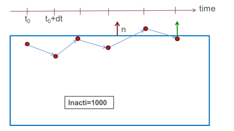
      Figure 2.

      inter_type24_inacti=1000
    • Inacti = -1: Initial forces are applied on all penetrating nodes. High initial penetrations should be avoided, as they might generate high contact forces and lead to high energy error at the beginning of the computation. The contact forces caused by the initial penetration are increased from zero at the contact activation time defined by Tstart or sens_ID to a maximum value Tpressfit after contact activation. The ramping of the contact forces caused by initial penetration allows for press fit situations in models to be simulated. To avoid dynamic effects, Tpressfit should not be too small. By default Tpressfit is the time corresponding to 10000 cycles.

      From version 2022.1, stiffness is determined automatically; for example, Istf, Stmin and Stmax have no effect, only Stfac can be used for stiffness scaling.

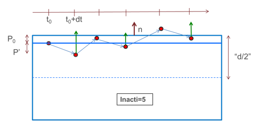
    • Inacti = 5: The main segment is shifted by the initial penetration value ( P 0 MathType@MTEF@5@5@+= feaagKart1ev2aqatCvAUfeBSjuyZL2yd9gzLbvyNv2CaerbuLwBLn hiov2DGi1BTfMBaeXatLxBI9gBaerbd9wDYLwzYbItLDharqqtubsr 4rNCHbGeaGqiVu0Je9sqqrpepC0xbbL8F4rqqrFfpeea0xe9Lq=Jc9 vqaqpepm0xbba9pwe9Q8fs0=yqaqpepae9pg0FirpepeKkFr0xfr=x fr=xb9adbaqaaeGaciGaaiaabeqaamaabaabaaGcbaGaamiuamaaBa aaleaacaaIWaaabeaaaaa@37B2@ ); therefore, at time zero no initial forces are applied.

    The main segment position is restored only in case of rebound larger than P 0 MathType@MTEF@5@5@+= feaagKart1ev2aqatCvAUfeBSjuyZL2yd9gzLbvyNv2CaerbuLwBLn hiov2DGi1BTfMBaeXatLxBI9gBaerbd9wDYLwzYbItLDharqqtubsr 4rNCHbGeaGqiVu0Je9sqqrpepC0xbbL8F4rqqrFfpeea0xe9Lq=Jc9 vqaqpepm0xbba9pwe9Q8fs0=yqaqpepae9pg0FirpepeKkFr0xfr=x fr=xb9adbaqaaeGaciGaaiaabeqaamaabaabaaGcbaGaamiuamaaBa aaleaacaaIWaaabeaaaaa@37B2@ .

    In the opposite case, when secondary node continues to penetrate, the penetration is computed as:
    P ' = P P 0
    Figure 3.

    inter_type24_inacti=5
    • Intersections and large initial penetration (Inacti= -2, -1 and 5):

      Shells and thick shells: initial intersections should be avoided, as they will lead to wrong direction of contact force and possible secondary nodes anchorage.

      Solids: by default, the distance which is considered for searching the initial penetration is compute as:

      d = m a i n s e g m e n t s 1 2 min [ V A , max e d g e = 1 , 4 ( L e d g e ) ] N _ m _ s e g

      While for each main segment,
      V MathType@MTEF@5@5@+= feaagKart1ev2aqatCvAUfeBSjuyZL2yd9gzLbvyNv2CaerbuLwBLn hiov2DGi1BTfMBaeXatLxBI9gBaerbd9wDYLwzYbItLDharqqtubsr 4rNCHbGeaGqiVu0Je9sqqrpepC0xbbL8F4rqqrFfpeea0xe9Lq=Jc9 vqaqpepm0xbba9pwe9Q8fs0=yqaqpepae9pg0FirpepeKkFr0xfr=x fr=xb9adbaqaaeGaciGaaiaabeqaamaabaabaaGcbaGaamOvaaaa@36D2@
      Volume of the connected solid element
      A MathType@MTEF@5@5@+= feaagKart1ev2aqatCvAUfeBSjuyZL2yd9gzLbvyNv2CaerbuLwBLn hiov2DGi1BTfMBaeXatLxBI9gBaerbd9wDYLwzYbItLDharqqtubsr 4rNCHbGeaGqiVu0Je9sqqrpepC0xbbL8F4rqqrFfpeea0xe9Lq=Jc9 vqaqpepm0xbba9pwe9Q8fs0=yqaqpepae9pg0FirpepeKkFr0xfr=x fr=xb9adbaqaaeGaciGaaiaabeqaamaabaabaaGcbaGaamyqaaaa@36BD@
      Segment area
      L e d g e
      e d g e MathType@MTEF@5@5@+= feaagKart1ev2aqatCvAUfeBSjuyZL2yd9gzLbvyNv2CaerbuLwBLn hiov2DGi1BTfMBaeXatLxBI9gBaerbd9wDYLwzYbItLDharqqtubsr 4rNCHbGeaGqiVu0Je9sqqrpepC0xbbL8F4rqqrFfpeea0xe9Lq=Jc9 vqaqpepm0xbba9pwe9Q8fs0=yqaqpepae9pg0FirpepeKkFr0xfr=x fr=xb9adbaqaaeGaciGaaiaabeqaamaabaabaaWcbaGaamyzaiaads gacaWGNbGaamyzaaaa@39A1@ = 1 to 4 are the lengths of the edges of the segment.
      N _ m _ s e g
      Number of main segments
      min [ V A , max e d g e = 1 , 4 ( L e d g e ) ]
      An estimation of the depth of the solid element connected to the segment (limited to the size of the segment)
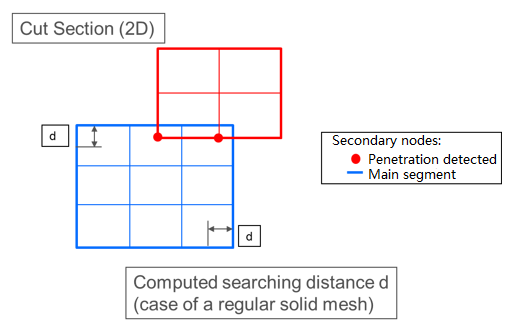
      Figure 4.

      inter_type24_cut_section
    Maximum initial penetration Ipen_max:
    • If a non-zero value is input for Ipen_max, this default value is omitted and initial penetrations will be searched within Ipen_max.
    • Large value of the searching distance might lead to poor performance of Radioss Starter and/or memory allocation failure. Therefore, it is advised not to set a too large value for Ipen_max.
    • Nevertheless, Ipen_max may be used to catch penetrations larger than the computed (default) searching distance, as shown in Figure 5:
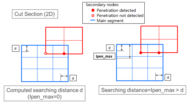
      Figure 5.

      inter_type24_sorting
  8. Ipen0, Initial penetration detection flag:
    • By default, the detection of the penetrations for self-impacts for each part (shell and solid elements only) are always excluded (even if surf_ID1 is defined in isolation and Inacti =-1 is set).
    • Ipen0 = 1 initial penetrations are taken into account for self-impact for each part and initial forces are set, but in some complex situations, incorrect initial penetrations might be calculated.
  9. When sens_ID is defined for activation/deactivation of the interface, Tstart and Tstop are not taken into account.
  10. When edge to edge contact is activated using I e d g e =1, the edge to edge contact is symmetric and the edges used in contact are automatically generated from the defined single surface (surf_ID1) or surface to surface contact (surf_ID1 and surf_ID2):
    • For solids and shells

      The edges are considered anywhere the angle between two external segments which share the same edge is smaller than Edge_angle value (by default 135°).

    • For shells
      The edges are considered at the perimeter border of the shell parts.
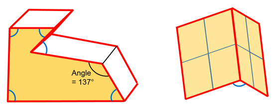
      Figure 6.


  11. For output forces:

    When the contact type is asymmetric surface to surface, the output normal contact forces in Time History are calculated correctly, if the two surfaces are well separated.

  12. For implicit solution:
    • Interface TYPE24 is only available with SMP
    • The default for Istf will be set to 4 (Istf=6 can be used, recommended for flexible or bending dominated structures)
    • The default for Inacti will be set to -1
  13. Contact Stiffness based on stability condition.

    This method is interesting to be used especially in cases materials have big stiffness difference. Stability condition stiffness is computed from the mass and time step:

    K m s d t = S f t a c m m m m s m m + m s 1 Δ t c 2 MathType@MTEF@5@5@+= feaahqart1ev3aaatCvAUfeBSjuyZL2yd9gzLbvyNv2CaerbuLwBLn hiov2DGi1BTfMBaeXatLxBI9gBaerbd9wDYLwzYbItLDharqqtubsr 4rNCHbGeaGqiVu0Je9sqqrpepC0xbbL8F4rqqrFfpeea0xe9Lq=Jc9 vqaqpepm0xbbG8FasPYRqj0=yi0dXdbba9pGe9xq=JbbG8A8frFve9 Fve9Ff0dmeaabaqaciGacaGaaeqabaWaaeaaeaaakeaacaWGlbWaaS baaSqaaiaad2gacaWGZbGaamizaiaadshaaeqaaOGaeyypa0Jaam4u aiaadAgacaWG0bGaamyyaiaadogacaWGTbGaeyyXIC9aaSaaaeaaca WGTbWaaSbaaSqaaiaad2gaaeqaaOGaeyyXICTaamyBamaaBaaaleaa caGGZbaabeaaaOqaaiaad2gadaWgaaWcbaGaamyBaaqabaGccqGHRa WkcaWGTbWaaSbaaSqaaiaadohaaeqaaaaakiabgwSixpaabmaabaWa aSaaaeaacaaIXaaabaGaeuiLdqKaamiDamaaBaaaleaacaWGJbaabe aaaaaakiaawIcacaGLPaaadaahaaWcbeqaaiaaikdaaaaaaa@58AC@

    Where,
    m m MathType@MTEF@5@5@+= feaahqart1ev3aaatCvAUfeBSjuyZL2yd9gzLbvyNv2CaerbuLwBLn hiov2DGi1BTfMBaeXatLxBI9gBaerbd9wDYLwzYbItLDharqqtubsr 4rNCHbGeaGqiVu0Je9sqqrpepC0xbbL8F4rqqrFfpeea0xe9Lq=Jc9 vqaqpepm0xbbG8FasPYRqj0=yi0dXdbba9pGe9xq=JbbG8A8frFve9 Fve9Ff0dmeaabaqaciGacaGaaeqabaWaaeaaeaaakeaacaWGTbWaaS baaSqaaiaad2gaaeqaaaaa@386B@ and m s MathType@MTEF@5@5@+= feaahqart1ev3aaatCvAUfeBSjuyZL2yd9gzLbvyNv2CaerbuLwBLn hiov2DGi1BTfMBaeXatLxBI9gBaerbd9wDYLwzYbItLDharqqtubsr 4rNCHbGeaGqiVu0Je9sqqrpepC0xbbL8F4rqqrFfpeea0xe9Lq=Jc9 vqaqpepm0xbbG8FasPYRqj0=yi0dXdbba9pGe9xq=JbbG8A8frFve9 Fve9Ff0dmeaabaqaciGacaGaaeqabaWaaeaaeaaakeaacaWGTbWaaS baaSqaaiaad2gaaeqaaaaa@386B@
    Main and secondary nodal masses.
    Δ t c MathType@MTEF@5@5@+= feaahqart1ev3aaatCvAUfeBSjuyZL2yd9gzLbvyNv2CaerbuLwBLn hiov2DGi1BTfMBaeXatLxBI9gBaerbd9wDYLwzYbItLDharqqtubsr 4rNCHbGeaGqiVu0Je9sqqrpepC0xbbL8F4rqqrFfpeea0xe9Lq=Jc9 vqaqpepm0xbbG8FasPYRqj0=yi0dXdbba9pGe9xq=JbbG8A8frFve9 Fve9Ff0dmeaabaqaciGacaGaaeqabaWaaeaaeaaakeaacqqHuoarca WG0bWaaSbaaSqaaiaadogaaeqaaaaa@39CE@
    Initial solution time step or the user input value Dtstif.

    If Istf = 7, the contact stiffness is only calculated based on the stability condition.

    K n = K m s d t MathType@MTEF@5@5@+= feaahqart1ev3aaatCvAUfeBSjuyZL2yd9gzLbvyNv2CaerbuLwBLn hiov2DGi1BTfMBaeXatLxBI9gBaerbd9wDYLwzYbItLDharqqtubsr 4rNCHbGeaGqiVu0Je9sqqrpepC0xbbL8F4rqqrFfpeea0xe9Lq=Jc9 vqaqpepm0xbbG8FasPYRqj0=yi0dXdbba9pGe9xq=JbbG8A8frFve9 Fve9Ff0dmeaabaqaciGacaGaaeqabaWaaeaaeaaakeaacaWGlbWaaS baaSqaaiaad6gaaeqaaOGaeyypa0Jaam4samaaBaaaleaacaWGTbGa am4CaiaadsgacaWG0baabeaaaaa@3E22@

    Otherwise, if Ipstif > 0, the stability condition stiffness K m s d t MathType@MTEF@5@5@+= feaahqart1ev3aaatCvAUfeBSjuyZL2yd9gzLbvyNv2CaerbuLwBLn hiov2DGi1BTfMBaeXatLxBI9gBaerbd9wDYLwzYbItLDharqqtubsr 4rNCHbGeaGqiVu0Je9sqqrpepC0xbbL8F4rqqrFfpeea0xe9Lq=Jc9 vqaqpepm0xbbG8FasPYRqj0=yi0dXdbba9pGe9xq=JbbG8A8frFve9 Fve9Ff0dmeaabaqaciGacaGaaeqabaWaaeaaeaaakeaacaWGlbWaaS baaSqaaiaad2gacaWGZbGaamizaiaadshaaeqaaaaa@3B23@ is used if it is greater than K n MathType@MTEF@5@5@+= feaahqart1ev3aaatCvAUfeBSjuyZL2yd9gzLbvyNv2CaerbuLwBLn hiov2DGi1BTfMBaeXatLxBI9gBaerbd9wDYLwzYbItLDharqqtubsr 4rNCHbGeaGqiVu0Je9sqqrpepC0xbbL8F4rqqrFfpeea0xe9Lq=Jc9 vqaqpepm0xbbG8FasPYRqj0=yi0dXdbba9pGe9xq=JbbG8A8frFve9 Fve9Ff0dmeaabaqaciGacaGaaeqabaWaaeaaeaaakeaacaWGlbWaaS baaSqaaiaad6gaaeqaaaaa@384A@ , stiffness defined by the flag Istf (see Comment 2).

    K = max S t min , min S t max , max ( K n , K m s d t ) MathType@MTEF@5@5@+= feaahqart1ev3aaatCvAUfeBSjuyZL2yd9gzLbvyNv2CaerbuLwBLn hiov2DGi1BTfMBaeXatLxBI9gBaerbd9wDYLwzYbItLDharqqtubsr 4rNCHbGeaGqiVu0Je9sqqrpepC0xbbL8F4rqqrFfpeea0xe9Lq=Jc9 vqaqpepm0xbbG8FasPYRqj0=yi0dXdbba9pGe9xq=JbbG8A8frFve9 Fve9Ff0dmeaabaqaciGacaGaaeqabaWaaeaaeaaakeaacaWGlbGaey ypa0JaciyBaiaacggacaGG4bWaamWaaeaacaWGtbGaamiDamaaBaaa leaaciGGTbGaaiyAaiaac6gaaeqaaOGaaiilaiGac2gacaGGPbGaai OBamaabmaabaGaam4uaiaadshadaWgaaWcbaGaciyBaiaacggacaGG 4baabeaakiaacYcaciGGTbGaaiyyaiaacIhacaGGOaGaam4samaaBa aaleaacaWGUbaabeaakiaacYcacaWGlbWaaSbaaSqaaiaad2gacaWG ZbGaamizaiaadshaaeqaaOGaaiykaaGaayjkaiaawMcaaaGaay5wai aaw2faaaaa@580E@

    By default, in case of contact stiffness based on stability condition (if Istf = 7 or Ipstif > 0), nodal masses used for K m s d t MathType@MTEF@5@5@+= feaahqart1ev3aaatCvAUfeBSjuyZL2yd9gzLbvyNv2CaerbuLwBLn hiov2DGi1BTfMBaeXatLxBI9gBaerbd9wDYLwzYbItLDharqqtubsr 4rNCHbGeaGqiVu0Je9sqqrpepC0xbbL8F4rqqrFfpeea0xe9Lq=Jc9 vqaqpepm0xbbG8FasPYRqj0=yi0dXdbba9pGe9xq=JbbG8A8frFve9 Fve9Ff0dmeaabaqaciGacaGaaeqabaWaaeaaeaaakeaacaWGlbWaaS baaSqaaiaad2gacaWGZbGaamizaiaadshaaeqaaaaa@3B23@ are calculated initially using the material density and elements size. It does not consider the added mass and can lead to low stiffness and contact instability. In that case, Ipstif= 2 can be used to consider initially added mass effect.

1 Chouly, Franz, and Yves Renard. "Explicit Verlet time-integration for a Nitsche-based approximation of elastodynamic contact problems." Advanced Modeling and Simulation in Engineering Sciences 5, no. 1 (2018): 31