/INTER/TYPE21

Block Format Keyword Specific interface between a non-deformable main surface and a secondary surface designed for stamping. All nodes of the main surface must belong to the rigid body.

Description

Features of this interface:
  • A node cannot be a secondary and a main node at the same time.
  • The normals to the main segments must be oriented toward the secondary surface.
  • For each secondary node, a single impact will be retained, in a way which ensures continuity of the normal force and the tangent force when this impact slides from one segment to a neighboring one.
  • Gap may vary according to the variation of shells and 3-node shells thickness, on the secondary side.
  • Fast search algorithm.
  • High speed-up with SPMD version.

Format

(1) (2) (3) (4) (5) (6) (7) (8) (9) (10)
/INTER/TYPE21/inter_ID/unit_ID
inter_title
surf_IDs surf_IDm Istf Ithe Igap     Idel Invn Iadm
Fscalegap Gapmax DEPTH Pmax ITlim  
Stmin Stmax     Pskid    
Stfac Fric Gapmin Tstart Tstop
IBC     Inacti VISs     Bumult
Ifric Ifiltr Xfreq   sens_ID fct_IDF AscaleF  
C1 C2 C3 C4 C5
C6        
NRadm Padm Angladm          
Kthe fct_IDK AscaleK Tint Ithe_form    
Frad Drad Fheat   fct_IDc Dcond
IDrby IDref Damp Dampr      

Definition

Field Contents SI Unit Example
inter_ID Interface identifier.

(Integer, maximum 10 digits)

 
unit_ID Unit Identifier.

(Integer, maximum 10 digits)

 
inter_title Interface title.

(Character, maximum 100 characters)

 
surf_IDs Secondary surface identifier.

(Integer)

 
surf_IDm Main surface identifier.

(Integer)

 
Istf Stiffness definition flag.
= 0
Stfac is a stiffness scale factor, and the stiffness is computed according to the secondary side characteristics.
= 1
Stfac is a stiffness value.

(Integer)

 
Ithe Heat transfer flag.
= 0
No heat transfer.
= 1
Heat transfer is activated, and the temperature of the tool is considered as constant (Tmain = Tint).
= 2
Heat transfer is activated and the temperature can be variable over the main surface and time.

(Integer)

 
Igap Gap/element option flag. 2
= 0
Gap is constant and equal to the minimum gap.
= 1
Gap is computed according to the characteristics of the secondary node. Gap does not take into account shells thickness change over time.
=2
Gap is computed according to the characteristics of the secondary node and will vary over time according to shells thickness change.

For Igap = 1 or 2, the thickness defined in the /PART card overrides the thickness defined in the property, initial state or shell element.

(Integer)

 
Idel Secondary node deletion flag.
=0 (Default)
No deletion of secondary nodes.
=1
When all the elements (4-node shells, 3-node shells, solids) associated to one secondary node are deleted, the secondary node is removed from the secondary side of the interface.

(Integer)

 
Invn Test flag for inverted main normals. 21
= 0 (Default)
Orientation of main normal will not be checked.
= 1
Orientation of main normal will be checked.

(Integer)

 
Iadm Computing local curvature flag for adaptive meshing. 3

(Integer)

 
Fscalegap Gap scale factor.

Default = 1.0 (Real)

 
Gapmax Maximum gap.

(Real)

[ m ]
DEPTH The drawbead depth. 4

(Real)

[ m ]
Pmax Maximum contact pressure, due to thickening. 5

Default = 1030 (Real)

[ Pa ]
ITlim Activate tangential force limitations. 5
= 0 (Default)
Tangential force is limited using Pmax.
= 1
Deactivates tangential force limitation.

(Integer)

 
Stmin Minimum stiffness.

(Real)

[ N m ]
Stmax Maximum stiffness.

Default = 1030 (Real)

[ N m ]
Pskid Maximum contact pressure used for defining a limit tangential force for skid line output (/H3D/NODA/SKID_LINE).

Default = 1030 (Real)

[ Pa ]
Stfac Interface stiffness (if Istf = 1).

Default set to 0.0 (Real)

[ N m ]
Stiffness scale factor for the interface (if Istf = 0).

Default set to 1.0 (Real)

Fric Coulomb friction (if fct_IDF = 0).

Default = 0.0 (Real)

 
Coulomb friction scale factor (if fct_IDF 0).

Default = 1.0 (Real)

Gapmin Minimum gap for impact activation.

(Real)

[ m ]
Tstart Start time.

(Real)

[ s ]
Tstop Time for temporary deactivation.

(Real)

[ s ]
IBC Deactivation flag of boundary conditions at impact.

(Boolean)

 
Inacti Deactivation flag of stiffness in case of initial penetrations. 9
= 0
No action.
= 1
Deactivation of stiffness on nodes.
= 5
Gap is variable with time and initial gap is computed as:
g a p 0 = G a p P 0 , with P 0 as the initial penetration.
= 6
Gap is variable with time, but initial penetration is computed as (the node is slightly depenetrated):
g a p 0 = G a p P 0 5 % ( G a p P 0 )

(Integer)

 
VISs Critical damping coefficient on interface stiffness.

Default set to 1.0 (Real)

 
Bumult Sorting factor is used to speed up the sorting algorithm. 10

Default set to 0.20 (Real)

 
Ifric Friction formulation flag. 12 13
= 0 (Default)
Static Coulomb friction law.
= 1
Generalized viscous friction law.
= 2
(Modified) Darmstad friction law.
= 3
Renard friction law.
= 4
Exponential decay friction law.

(Integer)

 
Ifiltr Friction filtering flag. 15
= 0 (Default)
No filter is used.
= 1
Simple numerical filter.
= 2
Standard -3dB filter with filtering period.
= 3
Standard -3dB filter with cutting frequency.

(Integer)

 
Xfreq Filtering coefficient. 15

(Real)

 
sens_ID Sensor identifier to activate/deactivate the interface. 20

If an identifier sensor is defined, the activation/deactivation of interface is based on sensor and not on Tstart or Tstop.

(Integer)

 
fct_IDF Function identifier for friction coefficient with temperature.

Default = 0 (Integer)

 
AscaleF Abscissa scale factor on fct_IDF.

Default = 1.0 (Real)

[ K ]
C1 - C6 Friction law coefficient.

(Real)

See Table 1
NRadm Number of elements through a 90° radius (used only if Iadm =2).

Default = 3 (Integer)

 
Padm Criteria on the percentage of penetration.

Default = 1.0 (Real)

 
Angladm Angle criteria.

(Real)

[ deg ]
Kthe Conductive heat exchange coefficient (if fct_IDK = 0).

Default = 0.0 (Real)

[ W m 2 K ]
Heat exchange scale factor (if fct_IDK0).

Default = 0.0 (Real)

 
fct_IDK Function identifier for heat exchange definition with contact pressure.

Default = 0 (Integer)

 
AscaleK Abscissa scale factor on fct_IDK.

Default = 1.0 (Real)

[ Pa ]
Tint Interface temperature.

(Real)

[ K ]
Ithe_form Heat contact formulation flag.
=0
Exchange only between interface (constant temperature) and shells (secondary side).
=1
Heat exchange between all pieces in contact.
0
Ithe must be equal to 2.

(Integer)

 
Frad Radiation factor. 17

(Real)

[ W m 2 K 4 ]
Drad Maximum distance for radiation computation.

(Real)

[ m ]
Fheat Frictional heating factor. 18

(Real)

 
fct_IDc Function identifier for the conductive heat exchange coefficient definition as a function of distance. 19

Default = 0 (Integer) 22

 
Dcond Maximum distance for conductive heat exchange. 23

Default = 0.0 (Real)

[ m ]
IDrby Rigid body identifier.

(Integer)

 
IDref Reference interface TYPE21 identifier for damping.
=0
Damping is proceeded, with respect to laboratory; otherwise, the relative velocity with the main surface of interface IDref, is damped.

(Integer)

 
Damp Translational critical damping factor. 19

(Real)

 
Dampr Rotational critical damping factor.

(Real)


Comments

  1. In case of SPMD, each main segment defined by surf_IDm must be associated to an element (possibly to a void element).
  2. Contact gap
    • If Igap = 0 (constant gap),

      Gap is constant over the secondary surface and along the time, equal to Gapmin. And a default value for Gapmin is computed as t / 2 , t being the average thickness of the secondary shell elements.

      In case of constant gap, Gapmax and Fscalegap will not be used.

    If contact thickness of the part is not defined in input /PART:
    • If Igap = 1, variable gap over the secondary surface is computed as:(1)
      max [ G a p min , min ( F s c a l e g a p g s , G a p max ) ] MathType@MTEF@5@5@+= feaagKart1ev2aaatCvAUfeBSjuyZL2yd9gzLbvyNv2CaerbuLwBLn hiov2DGi1BTfMBaeXatLxBI9gBaerbd9wDYLwzYbItLDharqqtubsr 4rNCHbGeaGqiVu0Je9sqqrpepC0xbbL8F4rqqrFfpeea0xe9Lq=Jc9 vqaqpepm0xbbG8FasPYRqj0=yi0dXdbba9pGe9xq=JbbG8A8frFve9 Fve9Ff0dmeaabaqaciGacaGaaeqabaWaaeaaeaaakeaaciGGTbGaai yyaiaacIhadaWadaqaaiaadEeacaWGHbGaamiCamaaBaaaleaaciGG TbGaaiyAaiaac6gaaeqaaOGaaiilaiGac2gacaGGPbGaaiOBamaabm aabaGaamOraiaadohacaWGJbGaamyyaiaadYgacaWGLbWaaSbaaSqa aiaadEgacaWGHbGaamiCaaqabaGccqGHflY1caWGNbWaaSbaaSqaai aadohaaeqaaOGaaiilaiaadEeacaWGHbGaamiCamaaBaaaleaaciGG TbGaaiyyaiaacIhaaeqaaaGccaGLOaGaayzkaaaacaGLBbGaayzxaa aaaa@590C@
    • If Igap = 2, variable gap over the secondary surface and along the time is computed at each time, as:(2)
      max [ G a p min , min ( F s c a l e g a p g s , G a p max ) ] MathType@MTEF@5@5@+= feaagKart1ev2aaatCvAUfeBSjuyZL2yd9gzLbvyNv2CaerbuLwBLn hiov2DGi1BTfMBaeXatLxBI9gBaerbd9wDYLwzYbItLDharqqtubsr 4rNCHbGeaGqiVu0Je9sqqrpepC0xbbL8F4rqqrFfpeea0xe9Lq=Jc9 vqaqpepm0xbbG8FasPYRqj0=yi0dXdbba9pGe9xq=JbbG8A8frFve9 Fve9Ff0dmeaabaqaciGacaGaaeqabaWaaeaaeaaakeaaciGGTbGaai yyaiaacIhadaWadaqaaiaadEeacaWGHbGaamiCamaaBaaaleaaciGG TbGaaiyAaiaac6gaaeqaaOGaaiilaiGac2gacaGGPbGaaiOBamaabm aabaGaamOraiaadohacaWGJbGaamyyaiaadYgacaWGLbWaaSbaaSqa aiaadEgacaWGHbGaamiCaaqabaGccqGHflY1caWGNbWaaSbaaSqaai aadohaaeqaaOGaaiilaiaadEeacaWGHbGaamiCamaaBaaaleaaciGG TbGaaiyyaiaacIhaaeqaaaGccaGLOaGaayzkaaaacaGLBbGaayzxaa aaaa@590C@

      and will vary along the time according to the variation of shells and 3-node shells thickness, on the secondary side.

      Where,
      g s
      Secondary node gap
      g s = t 2
      with t MathType@MTEF@5@5@+= feaagKart1ev2aaatCvAUfeBSjuyZL2yd9gzLbvyNv2CaerbuLwBLn hiov2DGi1BTfMBaeXatLxBI9gBaerbd9wDYLwzYbItLDharqqtubsr 4rNCHbGeaGqiVu0Je9sqqrpepC0xbbL8F4rqqrFfpeea0xe9Lq=Jc9 vqaqpepm0xbbG8FasPYRqj0=yi0dXdbba9pGe9xq=JbbG8A8frFve9 Fve9Ff0dmeaabaqaciGacaGaaeqabaWaaeaaeaaakeaacaWG0baaaa@3757@ is thickness of the secondary element for shell elements
      g s = 0
      For brick elements
    If contact thickness of the part is defined in input /PART:
    • If Igap = 1, variable gap is computed as:(3)
      max [ G a p min , min ( F s c a l e g a p t p a r t 2 , G a p max ) ] MathType@MTEF@5@5@+= feaagKart1ev2aaatCvAUfeBSjuyZL2yd9gzLbvyNv2CaerbuLwBLn hiov2DGi1BTfMBaeXatLxBI9gBaerbd9wDYLwzYbItLDharqqtubsr 4rNCHbGeaGqiVu0Je9sqqrpepC0xbbL8F4rqqrFfpeea0xe9Lq=Jc9 vqaqpepm0xbbG8FasPYRqj0=yi0dXdbba9pGe9xq=JbbG8A8frFve9 Fve9Ff0dmeaabaqaciGacaGaaeqabaWaaeaaeaaakeaaciGGTbGaai yyaiaacIhadaWadaqaaiaadEeacaWGHbGaamiCamaaBaaaleaaciGG TbGaaiyAaiaac6gaaeqaaOGaaiilaiGac2gacaGGPbGaaiOBamaabm aabaGaamOraiaadohacaWGJbGaamyyaiaadYgacaWGLbWaaSbaaSqa aiaadEgacaWGHbGaamiCaaqabaGccqGHflY1daWcaaqaaiaadshada WgaaWcbaGaamiCaiaadggacaWGYbGaamiDaaqabaaakeaacaaIYaaa aiaacYcacaWGhbGaamyyaiaadchadaWgaaWcbaGaciyBaiaacggaca GG4baabeaaaOGaayjkaiaawMcaaaGaay5waiaaw2faaaaa@5CB8@
    • If Igap = 2, variable gap is computed as:(4)
      max [ G a p min , min ( F s c a l e g a p t t 0 + t p a r t 2 , G a p max ) ] MathType@MTEF@5@5@+= feaagKart1ev2aaatCvAUfeBSjuyZL2yd9gzLbvyNv2CaerbuLwBLn hiov2DGi1BTfMBaeXatLxBI9gBaerbd9wDYLwzYbItLDharqqtubsr 4rNCHbGeaGqiVu0Je9sqqrpepC0xbbL8F4rqqrFfpeea0xe9Lq=Jc9 vqaqpepm0xbbG8FasPYRqj0=yi0dXdbba9pGe9xq=JbbG8A8frFve9 Fve9Ff0dmeaabaqaciGacaGaaeqabaWaaeaaeaaakeaaciGGTbGaai yyaiaacIhadaWadaqaaiaadEeacaWGHbGaamiCamaaBaaaleaaciGG TbGaaiyAaiaac6gaaeqaaOGaaiilaiGac2gacaGGPbGaaiOBamaabm aabaGaamOraiaadohacaWGJbGaamyyaiaadYgacaWGLbWaaSbaaSqa aiaadEgacaWGHbGaamiCaaqabaGccqGHflY1daWcaaqaaiaadshacq GHsislcaWG0bWaaSbaaSqaaiaaicdaaeqaaOGaey4kaSIaamiDamaa BaaaleaacaWGWbGaamyyaiaadkhacaWG0baabeaaaOqaaiaaikdaaa GaaiilaiaadEeacaWGHbGaamiCamaaBaaaleaaciGGTbGaaiyyaiaa cIhaaeqaaaGccaGLOaGaayzkaaaacaGLBbGaayzxaaaaaa@6169@
      Where,
      t p a r t MathType@MTEF@5@5@+= feaagKart1ev2aaatCvAUfeBSjuyZL2yd9gzLbvyNv2CaerbuLwBLn hiov2DGi1BTfMBaeXatLxBI9gBaerbd9wDYLwzYbItLDharqqtubsr 4rNCHbGeaGqiVu0Je9sqqrpepC0xbbL8F4rqqrFfpeea0xe9Lq=Jc9 vqaqpepm0xbbG8FasPYRqj0=yi0dXdbba9pGe9xq=JbbG8A8frFve9 Fve9Ff0dmeaabaqaciGacaGaaeqabaWaaeaaeaaakeaacaWG0bWaaS baaSqaaiaadchacaWGHbGaamOCaiaadshaaeqaaaaa@3B4E@
      Maximum thickness of the parts linked to the secondary node
      t MathType@MTEF@5@5@+= feaagKart1ev2aaatCvAUfeBSjuyZL2yd9gzLbvyNv2CaerbuLwBLn hiov2DGi1BTfMBaeXatLxBI9gBaerbd9wDYLwzYbItLDharqqtubsr 4rNCHbGeaGqiVu0Je9sqqrpepC0xbbL8F4rqqrFfpeea0xe9Lq=Jc9 vqaqpepm0xbbG8FasPYRqj0=yi0dXdbba9pGe9xq=JbbG8A8frFve9 Fve9Ff0dmeaabaqaciGacaGaaeqabaWaaeaaeaaakeaacaWG0baaaa@3757@
      Current thickness of the secondary node
      t 0 MathType@MTEF@5@5@+= feaagKart1ev2aaatCvAUfeBSjuyZL2yd9gzLbvyNv2CaerbuLwBLn hiov2DGi1BTfMBaeXatLxBI9gBaerbd9wDYLwzYbItLDharqqtubsr 4rNCHbGeaGqiVu0Je9sqqrpepC0xbbL8F4rqqrFfpeea0xe9Lq=Jc9 vqaqpepm0xbbG8FasPYRqj0=yi0dXdbba9pGe9xq=JbbG8A8frFve9 Fve9Ff0dmeaabaqaciGacaGaaeqabaWaaeaaeaaakeaacaWG0bWaaS baaSqaaiaaicdaaeqaaaaa@383D@
      Initial thickness of the secondary node

    If Igap = 1 or 2, the variable gap is always at most equal to Gapmax and default value for Gapmax will be set to 1030 and is always at least equal to Gapmin (but there is no default value for Gapmin).

  3. In case of adaptive meshing:
    • Iadm = 1:
      If the contact occurs in a zone (main side) whose radius of curvature is lower than the element size (secondary side), the element on the secondary side will be divided (if not yet at maximum level).

      inter_type7_Iadm
      Figure 1.
    • Iadm = 2:

      If the contact occurs in a zone (main side) whose radius of curvature is lower than NRadm times the element size (secondary side), the element on the secondary side will be divided (if not yet at maximum level).

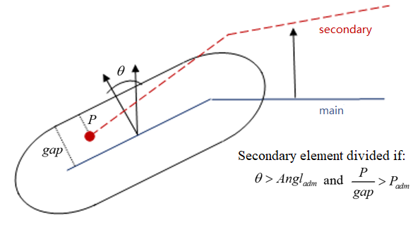
      If the contact occurs in a zone (main side) where the angles between the normals are greater than Angladm, and the percentage of penetration is greater than Padm, the element on the secondary side will be divided (if not yet at maximum level).

      inter_type21_angladm
      Figure 2.
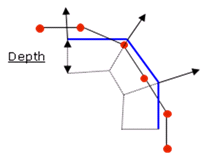
  4. The interface allows secondary nodes to cross the main surface; if a secondary node gets into the main surface from a distance greater than DEPTH, no contact force is computed on the node.

    inter_type21_depth
    Figure 3.
    A default value for DEPTH is computed as the maximum of:
    • Upper value of the gap (at time 0) among all nodes
    • Smallest side length of secondary element

    If the input value is not equal to 0, DEPTH will be raised up to the upper value of the gap (at time 0) among all nodes.

    Too large of a DEPTH will decrease the performances of search algorithms for contact.

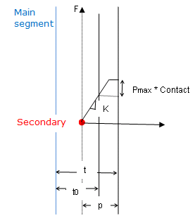
  5. Maximum contact pressure due to thickening. Pmax is used only if Igap = 2.
    • It can be used for limiting the contact force in case of thickening.
    • It can be used for limiting the normal contact force in case of thickening according to the following equation:(5)
      F n P max S
    • The tangent contact force is also limited when the flag ITlim = 0 by the following equation:(6)
      F t P max S 3

    Where, S MathType@MTEF@5@5@+= feaagKart1ev2aaatCvAUfeBSjuyZL2yd9gzLbvyNv2CaerbuLwBLn hiov2DGi1BTfMBaeXatLxBI9gBaerbd9wDYLwzYbItLDharqqtubsr 4rNCHbGeaGqiVu0Je9sqqrpepC0xbbL8F4rqqrFfpeea0xe9Lq=Jc9 vqaqpepm0xbbG8FasPYRqj0=yi0dXdbba9pGe9xq=JbbG8A8frFve9 Fve9Ff0dmeaabaqaciGacaGaaeqabaWaaeaaeaaakeaacaWGtbaaaa@3736@ is the extrapolated surface of segments connected to the secondary node.

  6. F = K

    inter_type21_pmax
    Figure 4.
  7. Stfac can be larger than 1.0.
  8. Deactivation of the boundary condition is applied to secondary nodes.
  9. Inacti = 3 may create initial energy if the node belongs to a spring element.

    Inacti = 5 or Inacti = 6, the gap is initially reduced and recovers its computed value as the secondary node depenetrates.

    Inacti = 6 is recommended instead of Inacti =5, to avoid high frequency effects into the interface.


    Figure 5.
  10. The default value for Bumult is automatically increased to 0.30 for models which have more than 1.5 million nodes and to 0.40 for models with more than 2.5 million of nodes.
  11. There is no limitation value to the stiffness factor (but a value larger than 1.0 can reduce the initial time step).
  12. For friction formulation
    • If the friction flag Ifric = 0 (default), the old static friction formulation is used:
      F t μ F n with μ is Coulomb Friction coefficient.
      • If fct_IDF = 0

        Fric is Coulomb friction

        μ = Fric

      • If fct_IDF0

        Fric becomes a scale factor of Coulomb friction coefficient which depends on the temperature.(7)
        μ = Fric f F ( A s c a l e F , T i n t e r f a c e )
        While, T i n t e r f a c e is the interface temperature which is taken as the mean temperature of secondary and main:(8)
        T i n t e r f a c e = T s e c o n d a r y + T m a i n 2
    • For flag Ifric > 0, new friction models are introduced. In this case, the friction coefficient is set by a function.(9)
      μ=μ(p,V) MathType@MTEF@5@5@+= feaagKart1ev2aqatCvAUfeBSjuyZL2yd9gzLbvyNv2CaerbuLwBLn hiov2DGi1BTfMBaeXatLxBI9gBaerbd9wDYLwzYbItLDharqqtubsr 4rNCHbGeaGqipu0Je9sqqrpepC0xbbL8F4rqqrFfpeea0xe9Lq=Jc9 vqaqpepm0xbba9pwe9Q8fs0=yqaqpepae9pg0FirpepeKkFr0xfr=x fr=xb9adbaqaaeGaciGaaiaabeqaamaabaabaaGcbaaeaaaaaaaaa8 qacqaH8oqBcqGH9aqpcaqG8oGaaiikaiaadchacaGGSaGaamOvaiaa cMcaaaa@3DCE@
      Where,
      p
      Pressure of the normal force on the main segment
      V
      Tangential velocity of the secondary node relative to the main segment
  13. Currently, the coefficients C1 through C6 are used (if Ifric = 0) and C6 is not used (if Ifric = 1) to define a variable friction coefficient μ for new friction formulations.
    The following formulations are available:
    • Ifric = 1 (Generalized Viscous Friction Law):(10)
      μ = Fric + C 1 p + C 2 V + C 3 p V + C 4 p 2 + C 5 V 2
    • Ifric = 2 (Modified Darmstad Law):(11)
      μ = F r i c + C 1 e ( C 2 V ) p 2 + C 3 e ( C 4 V ) p + C 5 e ( C 6 V )
    • Ifric = 3 (Renard law):

      μ = C 1 + ( C 3 C 1 ) V C 5 ( 2 V C 5 ) if V [ 0 , C 5 ]

      μ = C 3 ( ( C 3 C 4 ) ( V C 5 C 6 C 5 ) 2 ( 3 2 V C 5 C 6 C 5 ) ) if V [ C 5 , C 6 ]

      μ = C 2 1 1 C 2 C 4 + ( V C 6 ) 2 if V C 6

      Where,
      C 1 = μ s
      C 2 = μ d
      C 3 = μ max
      C 4 = μ min
      C 5 = V c r 1
      C 6 = V c r 2

      First critical velocity V c r 1 = C 5 must be different to 0 ( C 5 0 ).

      First critical velocity V c r 1 = C 5 must be lower than the second critical velocity V c r 2 = C 6 ( C 5 < C 6 ).

      The static friction coefficient C 1 and the dynamic friction coefficient C 2 , must be less than the maximum friction C 3 ( C 1 C 3 and C 2 C 3 ).

      The minimum friction coefficient C 4 must be less than the static friction coefficient C 1 and the dynamic friction coefficient C 2 ( C 4 C 1 and C 4 C 2 ).

    • Ifric = 4 (Exponential decay friction law)
      The frictional coefficient is assumed to be dependent on the relative velocity V MathType@MTEF@5@5@+= feaagKart1ev2aaatCvAUfeBSjuyZL2yd9gzLbvyNv2CaerbuLwBLn hiov2DGi1BTfMBaeXatLxBI9gBaerbd9wDYLwzYbItLDharqqtubsr 4rNCHbGeaGqiVu0Je9sqqrpepC0xbbL8F4rqqrFfpeea0xe9Lq=Jc9 vqaqpepm0xbba9pwe9Q8fs0=yqaqpepae9pg0FirpepeKkFr0xfr=x fr=xb9adbaqaaeGaciGaaiaabeqaamaabaabaaGcbaGaamOvaaaa@36D1@ of the surfaces in contact according to:(12)
      μ = C 1 + F r i c C 1 e C 2 V MathType@MTEF@5@5@+= feaahqart1ev3aqatCvAUfeBSjuyZL2yd9gzLbvyNv2CaerbuLwBLn hiov2DGi1BTfMBaeXatLxBI9gBaerbd9wDYLwzYbItLDharqqtubsr 4rNCHbGeaGqiVu0Je9sqqrpepC0xbbL8F4rqqrFfpeea0xe9Lq=Jc9 vqaqpepm0xbbG8FasPYRqj0=yi0dXdbba9pGe9xq=JbbG8A8frFve9 Fve9Ff0dmeaabaqaciGacaGaaeqabaWaaeaaeaaakeaacqaH8oqBcq GH9aqpcaWGdbWaaSbaaSqaaiaaigdaaeqaaOGaey4kaSYaaeWaaeaa caWGgbGaamOCaiaadMgacaWGJbGaeyOeI0Iaam4qamaaBaaaleaaca aIXaaabeaaaOGaayjkaiaawMcaaiabgwSixlaadwgadaahaaWcbeqa amaabmaabaGaeyOeI0Iaam4qamaaBaaameaacaaIYaaabeaalmaaem aabaGaamOvaaGaay5bSlaawIa7aaGaayjkaiaawMcaaaaaaaa@4F0A@
    Table 1. Units for Friction Formulations
    Ifric Fric C1 C2 C3 C4 C5 C6
    1 [ 1 P a ] MathType@MTEF@5@5@+= feaagKart1ev2aqatCvAUfeBSjuyZL2yd9gzLbvyNv2CaerbuLwBLn hiov2DGi1BTfMBaeXatLxBI9gBaerbd9wDYLwzYbItLDharqqtubsr 4rNCHbGeaGqiVu0Je9sqqrpepC0xbbL8F4rqqrFfpeea0xe9Lq=Jc9 vqaqpepm0xbbG8FasPYRqj0=yi0dXdbba9pGe9xq=JbbG8A8frFve9 Fve9Ff0dmeaabaqaciGacaGaaeqabaWaaeaaeaaakeaadaWadaqaam aalaaabaGaaGymaaqaaiaaccfacaGGHbaaaaGaay5waiaaw2faaaaa @3AD5@ [ s m ] MathType@MTEF@5@5@+= feaagKart1ev2aaatCvAUfeBSjuyZL2yd9gzLbvyNv2CaerbuLwBLn hiov2DGi1BTfMBaeXatLxBI9gBaerbd9wDYLwzYbItLDharqqtubsr 4rNCHbGeaGqiVu0Je9sqqrpepC0xbbL8F4rqqrFfpeea0xe9Lq=Jc9 vqaqpepm0xbbG8FasPYRqj0=yi0dXdbba9pGe9xq=JbbG8A8frFve9 Fve9Ff0dmeaabaqaciGacaGaaeqabaWaaeaaeaaakeaadaWadaqaam aalaaabaGaae4Caaqaaiaab2gaaaaacaGLBbGaayzxaaaaaa@3A46@ [ s Pa m ] MathType@MTEF@5@5@+= feaagKart1ev2aaatCvAUfeBSjuyZL2yd9gzLbvyNv2CaerbuLwBLn hiov2DGi1BTfMBaeXatLxBI9gBaerbd9wDYLwzYbItLDharqqtubsr 4rNCHbGeaGqiVu0Je9sqqrpepC0xbbL8F4rqqrFfpeea0xe9Lq=Jc9 vqaqpepm0xbbG8FasPYRqj0=yi0dXdbba9pGe9xq=JbbG8A8frFve9 Fve9Ff0dmeaabaqaciGacaGaaeqabaWaaeaaeaaakeaadaWadaqaam aalaaabaGaae4CaaqaaiaabcfacaqGHbGaeyyXICTaaeyBaaaaaiaa wUfacaGLDbaaaaa@3E47@ [ 1 Pa 2 ] MathType@MTEF@5@5@+= feaagKart1ev2aqatCvAUfeBSjuyZL2yd9gzLbvyNv2CaerbuLwBLn hiov2DGi1BTfMBaeXatLxBI9gBaerbd9wDYLwzYbItLDharqqtubsr 4rNCHbGeaGqiVu0Je9sqqrpepC0xbbL8F4rqqrFfpeea0xe9Lq=Jc9 vqaqpepm0xbbG8FasPYRqj0=yi0dXdbba9pGe9xq=JbbG8A8frFve9 Fve9Ff0dmeaabaqaciGacaGaaeqabaWaaeaaeaaakeaadaWadaqaam aalaaabaGaaGymaaqaaiaabcfacaqGHbWaaWbaaSqabeaacaaIYaaa aaaaaOGaay5waiaaw2faaaaa@3BC6@ [ s 2 m 2 ] MathType@MTEF@5@5@+= feaagKart1ev2aaatCvAUfeBSjuyZL2yd9gzLbvyNv2CaerbuLwBLn hiov2DGi1BTfMBaeXatLxBI9gBaerbd9wDYLwzYbItLDharqqtubsr 4rNCHbGeaGqiVu0Je9sqqrpepC0xbbL8F4rqqrFfpeea0xe9Lq=Jc9 vqaqpepm0xbbG8FasPYRqj0=yi0dXdbba9pGe9xq=JbbG8A8frFve9 Fve9Ff0dmeaabaqaciGacaGaaeqabaWaaeaaeaaakeaadaWadaqaam aalaaabaGaae4CamaaCaaaleqabaGaaGOmaaaaaOqaaiaab2gadaah aaWcbeqaaiaaikdaaaaaaaGccaGLBbGaayzxaaaaaa@3C2C@
    2 [ 1 Pa 2 ] MathType@MTEF@5@5@+= feaagKart1ev2aqatCvAUfeBSjuyZL2yd9gzLbvyNv2CaerbuLwBLn hiov2DGi1BTfMBaeXatLxBI9gBaerbd9wDYLwzYbItLDharqqtubsr 4rNCHbGeaGqiVu0Je9sqqrpepC0xbbL8F4rqqrFfpeea0xe9Lq=Jc9 vqaqpepm0xbbG8FasPYRqj0=yi0dXdbba9pGe9xq=JbbG8A8frFve9 Fve9Ff0dmeaabaqaciGacaGaaeqabaWaaeaaeaaakeaadaWadaqaam aalaaabaGaaGymaaqaaiaabcfacaqGHbWaaWbaaSqabeaacaaIYaaa aaaaaOGaay5waiaaw2faaaaa@3BC6@ [ s m ] MathType@MTEF@5@5@+= feaagKart1ev2aaatCvAUfeBSjuyZL2yd9gzLbvyNv2CaerbuLwBLn hiov2DGi1BTfMBaeXatLxBI9gBaerbd9wDYLwzYbItLDharqqtubsr 4rNCHbGeaGqiVu0Je9sqqrpepC0xbbL8F4rqqrFfpeea0xe9Lq=Jc9 vqaqpepm0xbbG8FasPYRqj0=yi0dXdbba9pGe9xq=JbbG8A8frFve9 Fve9Ff0dmeaabaqaciGacaGaaeqabaWaaeaaeaaakeaadaWadaqaam aalaaabaGaae4Caaqaaiaab2gaaaaacaGLBbGaayzxaaaaaa@3A46@ [ 1 P a ] MathType@MTEF@5@5@+= feaagKart1ev2aqatCvAUfeBSjuyZL2yd9gzLbvyNv2CaerbuLwBLn hiov2DGi1BTfMBaeXatLxBI9gBaerbd9wDYLwzYbItLDharqqtubsr 4rNCHbGeaGqiVu0Je9sqqrpepC0xbbL8F4rqqrFfpeea0xe9Lq=Jc9 vqaqpepm0xbbG8FasPYRqj0=yi0dXdbba9pGe9xq=JbbG8A8frFve9 Fve9Ff0dmeaabaqaciGacaGaaeqabaWaaeaaeaaakeaadaWadaqaam aalaaabaGaaGymaaqaaiaaccfacaGGHbaaaaGaay5waiaaw2faaaaa @3AD5@ [ s m ] MathType@MTEF@5@5@+= feaagKart1ev2aaatCvAUfeBSjuyZL2yd9gzLbvyNv2CaerbuLwBLn hiov2DGi1BTfMBaeXatLxBI9gBaerbd9wDYLwzYbItLDharqqtubsr 4rNCHbGeaGqiVu0Je9sqqrpepC0xbbL8F4rqqrFfpeea0xe9Lq=Jc9 vqaqpepm0xbbG8FasPYRqj0=yi0dXdbba9pGe9xq=JbbG8A8frFve9 Fve9Ff0dmeaabaqaciGacaGaaeqabaWaaeaaeaaakeaadaWadaqaam aalaaabaGaae4Caaqaaiaab2gaaaaacaGLBbGaayzxaaaaaa@3A46@ [ s m ] MathType@MTEF@5@5@+= feaagKart1ev2aaatCvAUfeBSjuyZL2yd9gzLbvyNv2CaerbuLwBLn hiov2DGi1BTfMBaeXatLxBI9gBaerbd9wDYLwzYbItLDharqqtubsr 4rNCHbGeaGqiVu0Je9sqqrpepC0xbbL8F4rqqrFfpeea0xe9Lq=Jc9 vqaqpepm0xbbG8FasPYRqj0=yi0dXdbba9pGe9xq=JbbG8A8frFve9 Fve9Ff0dmeaabaqaciGacaGaaeqabaWaaeaaeaaakeaadaWadaqaam aalaaabaGaae4Caaqaaiaab2gaaaaacaGLBbGaayzxaaaaaa@3A46@
    3 [ m s ] MathType@MTEF@5@5@+= feaagKart1ev2aaatCvAUfeBSjuyZL2yd9gzLbvyNv2CaerbuLwBLn hiov2DGi1BTfMBaeXatLxBI9gBaerbd9wDYLwzYbItLDharqqtubsr 4rNCHbGeaGqiVu0Je9sqqrpepC0xbbL8F4rqqrFfpeea0xe9Lq=Jc9 vqaqpepm0xbba9pwe9Q8fs0=yqaqpepae9pg0FirpepeKkFr0xfr=x fr=xb9adbaqaaeGaciGaaiaabeqaamaabaabaaGcbaWaamWaaeaada Wcaaqaaiaab2gaaeaacaqGZbaaaaGaay5waiaaw2faaaaa@39DE@ [ m s ] MathType@MTEF@5@5@+= feaagKart1ev2aaatCvAUfeBSjuyZL2yd9gzLbvyNv2CaerbuLwBLn hiov2DGi1BTfMBaeXatLxBI9gBaerbd9wDYLwzYbItLDharqqtubsr 4rNCHbGeaGqiVu0Je9sqqrpepC0xbbL8F4rqqrFfpeea0xe9Lq=Jc9 vqaqpepm0xbba9pwe9Q8fs0=yqaqpepae9pg0FirpepeKkFr0xfr=x fr=xb9adbaqaaeGaciGaaiaabeqaamaabaabaaGcbaWaamWaaeaada Wcaaqaaiaab2gaaeaacaqGZbaaaaGaay5waiaaw2faaaaa@39DE@
    4     [ s m ] MathType@MTEF@5@5@+= feaagKart1ev2aaatCvAUfeBSjuyZL2yd9gzLbvyNv2CaerbuLwBLn hiov2DGi1BTfMBaeXatLxBI9gBaerbd9wDYLwzYbItLDharqqtubsr 4rNCHbGeaGqiVu0Je9sqqrpepC0xbbL8F4rqqrFfpeea0xe9Lq=Jc9 vqaqpepm0xbbG8FasPYRqj0=yi0dXdbba9pGe9xq=JbbG8A8frFve9 Fve9Ff0dmeaabaqaciGacaGaaeqabaWaaeaaeaaakeaadaWadaqaam aalaaabaGaae4Caaqaaiaab2gaaaaacaGLBbGaayzxaaaaaa@3A46@        
  14. The formulation for friction is a stiffness (incremental) formulation, and the friction forces are:(13)
    F t n e w = min ( μ F n , F a d h )

    While an adhesion force is computed as:

    F a d h = F t o l d + Δ F t with Δ F t = K V t d t

    Where, V t is the tangential relative velocity of the secondary node with the main segment.

  15. Friction filtering
    If Ifiltr0, the tangential forces are smoothed using a filter:(14)
    F T f = α F T ( t ) + 1 α F T f ( t d t ) MathType@MTEF@5@5@+= feaahqart1ev3aaatCvAUfeBSjuyZL2yd9gzLbvyNv2CaerbuLwBLn hiov2DGi1BTfMBaeXatLxBI9gBaerbd9wDYLwzYbItLDharqqtubsr 4rNCHbGeaGqiVu0Je9sqqrpepC0xbbL8F4rqqrFfpeea0xe9Lq=Jc9 vqaqpepm0xbba9pwe9Q8fs0=yqaqpepae9pg0FirpepeKkFr0xfr=x fr=xb9adbaqaaeGaciGaaiaabeqaamaabaabaaGcbaGaaCOramaaBa aaleaacaWGubGaamOzaaqabaGccqGH9aqpcqaHXoqycaWHgbWaaSba aSqaaiaadsfaaeqaaOGaaiikaiaadshacaGGPaGaey4kaSYaaeWaae aacaaIXaGaeyOeI0IaeqySdegacaGLOaGaayzkaaGaaCOramaaBaaa leaacaWGubGaamOzaaqabaGccaGGOaGaamiDaiabgkHiTiaadsgaca WG0bGaaiykaaaa@4D2D@
    Where,
    F T f MathType@MTEF@5@5@+= feaahqart1ev3aaatCvAUfeBSjuyZL2yd9gzLbvyNv2CaerbuLwBLn hiov2DGi1BTfMBaeXatLxBI9gBaerbd9wDYLwzYbItLDharqqtubsr 4rNCHbGeaGqiVu0Je9sqqrpepC0xbbL8F4rqqrFfpeea0xe9Lq=Jc9 vqaqpepm0xbba9pwe9Q8fs0=yqaqpepae9pg0FirpepeKkFr0xfr=x fr=xb9adbaqaaeGaciGaaiaabeqaamaabaabaaGcbaGaaCOramaaBa aaleaacaWGubGaamOzaaqabaaaaa@38B2@
    Filtered tangential force
    F T ( t ) MathType@MTEF@5@5@+= feaahqart1ev3aaatCvAUfeBSjuyZL2yd9gzLbvyNv2CaerbuLwBLn hiov2DGi1BTfMBaeXatLxBI9gBaerbd9wDYLwzYbItLDharqqtubsr 4rNCHbGeaGqiVu0Je9sqqrpepC0xbbL8F4rqqrFfpeea0xe9Lq=Jc9 vqaqpepm0xbba9pwe9Q8fs0=yqaqpepae9pg0FirpepeKkFr0xfr=x fr=xb9adbaqaaeGaciGaaiaabeqaamaabaabaaGcbaGaaCOramaaBa aaleaacaWGubaabeaakiaacIcacaWG0bGaaiykaaaa@3A23@
    Calculated tangential force at time t MathType@MTEF@5@5@+= feaahqart1ev3aaatCvAUfeBSjuyZL2yd9gzLbvyNv2CaerbuLwBLn hiov2DGi1BTfMBaeXatLxBI9gBaerbd9wDYLwzYbItLDharqqtubsr 4rNCHbGeaGqiVu0Je9sqqrpepC0xbbL8F4rqqrFfpeea0xe9Lq=Jc9 vqaqpepm0xbba9pwe9Q8fs0=yqaqpepae9pg0FirpepeKkFr0xfr=x fr=xb9adbaqaaeGaciGaaiaabeqaamaabaabaaGcbaGaamiDaaaa@36EC@ before filtering
    F T f ( t d t ) MathType@MTEF@5@5@+= feaahqart1ev3aaatCvAUfeBSjuyZL2yd9gzLbvyNv2CaerbuLwBLn hiov2DGi1BTfMBaeXatLxBI9gBaerbd9wDYLwzYbItLDharqqtubsr 4rNCHbGeaGqiVu0Je9sqqrpepC0xbbL8F4rqqrFfpeea0xe9Lq=Jc9 vqaqpepm0xbba9pwe9Q8fs0=yqaqpepae9pg0FirpepeKkFr0xfr=x fr=xb9adbaqaaeGaciGaaiaabeqaamaabaabaaGcbaGaaCOramaaBa aaleaacaWGubGaamOzaaqabaGccaGGOaGaamiDaiabgkHiTiaadsga caWG0bGaaiykaaaa@3DDD@
    Filtered tangential force at the previous time step
    t MathType@MTEF@5@5@+= feaahqart1ev3aaatCvAUfeBSjuyZL2yd9gzLbvyNv2CaerbuLwBLn hiov2DGi1BTfMBaeXatLxBI9gBaerbd9wDYLwzYbItLDharqqtubsr 4rNCHbGeaGqiVu0Je9sqqrpepC0xbbL8F4rqqrFfpeea0xe9Lq=Jc9 vqaqpepm0xbba9pwe9Q8fs0=yqaqpepae9pg0FirpepeKkFr0xfr=x fr=xb9adbaqaaeGaciGaaiaabeqaamaabaabaaGcbaGaamiDaaaa@36EC@
    Current simulation time
    d t MathType@MTEF@5@5@+= feaahqart1ev3aaatCvAUfeBSjuyZL2yd9gzLbvyNv2CaerbuLwBLn hiov2DGi1BTfMBaeXatLxBI9gBaerbd9wDYLwzYbItLDharqqtubsr 4rNCHbGeaGqiVu0Je9sqqrpepC0xbbL8F4rqqrFfpeea0xe9Lq=Jc9 vqaqpepm0xbba9pwe9Q8fs0=yqaqpepae9pg0FirpepeKkFr0xfr=x fr=xb9adbaqaaeGaciGaaiaabeqaamaabaabaaGcbaGaamizaiaads haaaa@37D5@
    Current simulation time step
    α MathType@MTEF@5@5@+= feaahqart1ev3aqatCvAUfeBSjuyZL2yd9gzLbvyNv2CaerbuLwBLn hiov2DGi1BTfMBaeXatLxBI9gBaerbd9wDYLwzYbItLDharqqtubsr 4rNCHbGeaGqiVu0Je9sqqrpepC0xbbL8F4rqqrFfpeea0xe9Lq=Jc9 vqaqpepm0xbba9pwe9Q8fs0=yqaqpepae9pg0FirpepeKkFr0xfr=x fr=xb9adbaqaaeGaciGaaiaabeqaamaabaabaaGcbaGaeqySdegaaa@3793@
    Filtering coefficient
    Where, α MathType@MTEF@5@5@+= feaahqart1ev3aqatCvAUfeBSjuyZL2yd9gzLbvyNv2CaerbuLwBLn hiov2DGi1BTfMBaeXatLxBI9gBaerbd9wDYLwzYbItLDharqqtubsr 4rNCHbGeaGqiVu0Je9sqqrpepC0xbbL8F4rqqrFfpeea0xe9Lq=Jc9 vqaqpepm0xbba9pwe9Q8fs0=yqaqpepae9pg0FirpepeKkFr0xfr=x fr=xb9adbaqaaeGaciGaaiaabeqaamaabaabaaGcbaGaeqySdegaaa@3793@ coefficient is calculated from, if:
    • Ifiltr =1 α = X f r e q , simple numerical filter with a value between 0 and 1.
    • Ifiltr =2 α = 2 π X f r e q , standard -3dB filter, with the number of time steps to filter defined as X f r e q = d t T , and T = filtering period
    • Ifiltr =3 α = 2 π X f r e q d t standard -3dB filter, with Xfreq = cutting frequency
  16. Heat exchange
    By Ithe= 1 (heat transfer activated) to consider heat exchange and heat friction in contact.
    • If Ithe_form =0, then heat exchange is between shell and constant temperature contact Tint.
    • If Ithe_form =1, then heat exchange is between all contact pieces.

    Tint is used only when Ithe_form= 0. In this case. The temperature of main side assumed to be constant (equal to Tint). If Ithe_form= 1, then Tint is not taken into account. So the nodal temperature of main side will be considered.

    If Ithe = 2, Heat transfer is computed using thermal conductance Kthe only for the secondary side. The temperature of the main side is not assumed to be a constant but is calculated from the temperature field defined on each main node. These nodal temperatures can vary over time and space which are defined using /IMPTEMP.

    Thermal conduction

    Ithe = 1 needs the material of the secondary side to be a thermal material using finite element formulation for heat transfer (/HEAT/MAT).

    Thermal conduction is computed when the secondary node falls into gap:(15)
    g a p = max [ G a p min , min ( Fscal e g a p g s , G a p max ) ]
    Heat exchange coefficient
    • If fct_IDK = 0, then Kthe is heat exchange coefficient and heat exchange depends only on heat exchange surface.
    • If fct_IDK0, Kthe is a scale factor and heat exchange depends on contact pressure:(16)
      K = K t h e f K ( A s c a l e K , P )

      While f K is the function of fct_IDK.

  17. Radiation:
    Radiation is considered in contact if F r a d 0 and the distance, d MathType@MTEF@5@5@+= feaagKart1ev2aqatCvAUfeBSjuyZL2yd9gzLbvyNv2CaerbuLwBLn hiov2DGi1BTfMBaeXatLxBI9gBaerbd9wDYLwzYbItLDharqqtubsr 4rNCHbGeaGqiVu0Je9sqqrpepC0xbbL8F4rqqrFfpeea0xe9Lq=Jc9 vqaqpepm0xbbG8FasPYRqj0=yi0dXdbba9pGe9xq=JbbG8A8frFve9 Fve9Ff0dmeaabaqaciGacaGaaeqabaWaaeaaeaaakeaacaWGebWaaS baaSqaaiaadkhacaWGHbGaamizaaqabaaaaa@3A1A@ , of the secondary node to the main segment is:(17)
    Gap < d < D rad
    While D r a d MathType@MTEF@5@5@+= feaagKart1ev2aqatCvAUfeBSjuyZL2yd9gzLbvyNv2CaerbuLwBLn hiov2DGi1BTfMBaeXatLxBI9gBaerbd9wDYLwzYbItLDharqqtubsr 4rNCHbGeaGqiVu0Je9sqqrpepC0xbbL8F4rqqrFfpeea0xe9Lq=Jc9 vqaqpepm0xbbG8FasPYRqj0=yi0dXdbba9pGe9xq=JbbG8A8frFve9 Fve9Ff0dmeaabaqaciGacaGaaeqabaWaaeaaeaaakeaacaWGebWaaS baaSqaaiaadkhacaWGHbGaamizaaqabaaaaa@3A1A@ is the maximum distance for radiation computation. The default value for D r a d MathType@MTEF@5@5@+= feaagKart1ev2aqatCvAUfeBSjuyZL2yd9gzLbvyNv2CaerbuLwBLn hiov2DGi1BTfMBaeXatLxBI9gBaerbd9wDYLwzYbItLDharqqtubsr 4rNCHbGeaGqiVu0Je9sqqrpepC0xbbL8F4rqqrFfpeea0xe9Lq=Jc9 vqaqpepm0xbbG8FasPYRqj0=yi0dXdbba9pGe9xq=JbbG8A8frFve9 Fve9Ff0dmeaabaqaciGacaGaaeqabaWaaeaaeaaakeaacaWGebWaaS baaSqaaiaadkhacaWGHbGaamizaaqabaaaaa@3A1A@ is computed as the maximum of:
    • Upper value of the Gap (at time 0) among all nodes
    • Smallest side length of secondary element

    It is recommended not to set the value too high for D r a d MathType@MTEF@5@5@+= feaagKart1ev2aqatCvAUfeBSjuyZL2yd9gzLbvyNv2CaerbuLwBLn hiov2DGi1BTfMBaeXatLxBI9gBaerbd9wDYLwzYbItLDharqqtubsr 4rNCHbGeaGqiVu0Je9sqqrpepC0xbbL8F4rqqrFfpeea0xe9Lq=Jc9 vqaqpepm0xbbG8FasPYRqj0=yi0dXdbba9pGe9xq=JbbG8A8frFve9 Fve9Ff0dmeaabaqaciGacaGaaeqabaWaaeaaeaaakeaacaWGebWaaS baaSqaaiaadkhacaWGHbGaamizaaqabaaaaa@3A1A@ , which may reduce the performance of Radioss Engine.

    A radiant heat transfer conductance is computed as:(18)
    h rad = F rad ( T m 2 + T s 2 ) ( T m + T s )
    with(19)
    F rad = σ 1 ε 1 + 1 ε 2 1
    Where,
    σ = 5.669 × 10 8 [ W m 2 K 4 ]
    Stefan Boltzman constant
    ε 1
    Emissivity of secondary surface
    ε 2
    Emissivity of main surface
  18. Heat Friction
    • Frictional energy is converted into heat when Ithe > 0 for interface
    • Fheat is defined as the fraction of this energy which is converted into heat and transferred to the secondary side.
    • The frictional heat QFric is so defined for a stiffness formulation:(20)
      Q Fric = F h e a t ( F a d h F t ) K F t
  19. Critical damping factors allow for the reduction of dynamic effects, especially for those tools where a loading is applied. This can be used to model the hydraulic press system:

    A damping force (resp. torque) is applied to the tool:

    F d = C v (resp.) m d = C r v r

    With C = D a m p 2 M a s s K resp. C r = D a m p r 2 I K r

    Where,
    C
    Percentage of the critical damping with the tool mass Mass (resp. inertia I MathType@MTEF@5@5@+= feaagKart1ev2aqatCvAUfeBSjuyZL2yd9gzLbvyNv2CaerbuLwBLn hiov2DGi1BTfMBaeXatLxBI9gBaerbd9wDYLwzYbItLDharqqtubsr 4rNCHbGeaGqiVu0Je9sqqrpepC0xbbL8F4rqqrFfpeea0xe9Lq=Jc9 vqaqpepm0xbba9pwe9Q8fs0=yqaqpepae9pg0FirpepeKkFr0xfr=x fr=xb9adbaqaaeGaciGaaiaabeqaamaabaabaaGcbaGaamysaaaa@36C5@ ).
    K
    Total interface stiffness (resp. rotational stiffness K r MathType@MTEF@5@5@+= feaagKart1ev2aqatCvAUfeBSjuyZL2yd9gzLbvyNv2CaerbuLwBLn hiov2DGi1BTfMBaeXatLxBI9gBaerbd9wDYLwzYbItLDharqqtubsr 4rNCHbGeaGqiVu0Je9sqqrpepC0xbbL8F4rqqrFfpeea0xe9Lq=Jc9 vqaqpepm0xbba9pwe9Q8fs0=yqaqpepae9pg0FirpepeKkFr0xfr=x fr=xb9adbaqaaeGaciGaaiaabeqaamaabaabaaGcbaGaam4samaaBa aaleaacaWGYbaabeaaaaa@37EA@ ).
    v (resp. ) v r
    Translational (resp. rotational) velocity of the tool, if IDref is equal to 0; otherwise, it is the relative velocity with respect to tool of interface IDref.
  20. When sens_ID is defined for activation/deactivation of the interface, Tstart and Tstop are not taken into account.
  21. If Invn = 1, Radioss will check if main normal are oriented towards the blank or not. Not well oriented normal may cause big penetrations and wrong results. If this happens, it is important to stop computation when this problem is detected. This option used to check if secondary node is contacting the main segment from the correct side (Figure 6) at the time of first impact. If not, the computation is stopped with an error message.


    Figure 6.
    • Main normal is well oriented: First impact is from correct side (penetration is smaller than Gap).
    • Main normal is not well oriented: First impact is from wrong side (penetration is almost equal to DEPTH).

    This option is only available for shells and must be used with a special care, because the computation can be stopped even if the normals are well oriented when there are large initial penetrations.

  22. When fct_IDc ≠0, the heat transfer coefficient can change as function of distance d when Gap < dDcond.

    Abscises and ordinates of this function must be between 0 and 1.

    The heat transfer coefficient is computed as:(21)
    K= K the ( P=0 )*fct_I D c ( dGap DcondGap ) MathType@MTEF@5@5@+= feaagKart1ev2aqatCvAUfeBSjuyZL2yd9gzLbvyNv2CaerbuLwBLn hiov2DGi1BTfMBaeXatLxBI9gBaerbd9wDYLwzYbItLDharqqtubsr 4rNCHbGeaGqiVCI8FfYJH8YrFfeuY=Hhbbf9v8qqaqFr0xc9pk0xbb a9q8WqFfeaY=biLkVcLq=JHqpepeea0=as0Fb9pgeaYRXxe9vr0=vr 0=vqpWqaaeaabiGaciaacaqabeaadaqaaqaaaOqaaabaaaaaaaaape Gaam4saiabg2da9iaadUeadaWgaaWcbaGaamiDaiaadIgacaWGLbaa beaakmaabmaapaqaa8qacaWGqbGaeyypa0JaaGimaaGaayjkaiaawM caaiaacQcacaWGMbGaam4yaiaadshacaaMb8Uaai4xaiaaxcW7caWG jbGaamiramaaBaaaleaacaWGJbaabeaakmaabmaapaqaa8qadaWcaa WdaeaapeGaamizaiabgkHiTiaadEeacaWGHbGaamiCaaWdaeaapeGa amiraiaadogacaWGVbGaamOBaiaadsgacqGHsislcaWGhbGaamyyai aadchaaaaacaGLOaGaayzkaaaaaa@58A1@

    The maximum value of K MathType@MTEF@5@5@+= feaagKart1ev2aqatCvAUfeBSjuyZL2yd9gzLbvyNv2CaerbuLwBLn hiov2DGi1BTfMBaeXatLxBI9gBaerbd9wDYLwzYbItLDharqqtubsr 4rNCHbGeaGqiVCI8FfYJH8YrFfeuY=Hhbbf9v8qqaqFr0xc9pk0xbb a9q8WqFfeaY=biLkVcLq=JHqpepeea0=as0Fb9pgeaYRXxe9vr0=vr 0=vqpWqaaeaabiGaciaacaqabeaadaqaaqaaaOqaaabaaaaaaaaape Gaam4saaaa@36DC@ is equal to the value of Kthe when Kthe is constant. Otherwise, in case of Kthe depending on pressure, the maximum is equal to value of Kthe for contact pressure P MathType@MTEF@5@5@+= feaagKart1ev2aqatCvAUfeBSjuyZL2yd9gzLbvyNv2CaerbuLwBLn hiov2DGi1BTfMBaeXatLxBI9gBaerbd9wDYLwzYbItLDharqqtubsr 4rNCHbGeaGqiVCI8FfYJH8YrFfeuY=Hhbbf9v8qqaqFr0xc9pk0xbb a9q8WqFfeaY=biLkVcLq=JHqpepeea0=as0Fb9pgeaYRXxe9vr0=vr 0=vqpWqaaeaabiGaciaacaqabeaadaqaaqaaaOqaaabaaaaaaaaape Gaam4saaaa@36DC@ =0.

    K MathType@MTEF@5@5@+= feaagKart1ev2aqatCvAUfeBSjuyZL2yd9gzLbvyNv2CaerbuLwBLn hiov2DGi1BTfMBaeXatLxBI9gBaerbd9wDYLwzYbItLDharqqtubsr 4rNCHbGeaGqiVCI8FfYJH8YrFfeuY=Hhbbf9v8qqaqFr0xc9pk0xbb a9q8WqFfeaY=biLkVcLq=JHqpepeea0=as0Fb9pgeaYRXxe9vr0=vr 0=vqpWqaaeaabiGaciaacaqabeaadaqaaqaaaOqaaabaaaaaaaaape Gaam4saaaa@36DC@ drops to zero when distance is equal to Dcond.

  23. When fct_IDc≠0, the heat transfer is computed as:
    • Conductive heat transfer when d < Gap
    • Conductive and radiative heat transfer when Gap < dDcond.
    • Radiative heat transfer when Dcond < dDrad
  24. When fct_IDc ≠ 0 and Dcond = 0, then Dcond=Drad.

    When Frad ≠ 0, fct_IDc ≠ 0, and Drad = 0, then Drad = Dcond.