OS-E: 0185 Rubber Ring: Crush and Slide Using Self-Contact
Demonstrates self-contact which is used in this nonlinear large displacement implicit analysis involving hyperelastic material and contacts using OptiStruct.
Model Files
Model Description
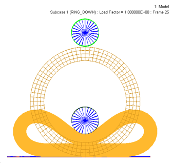
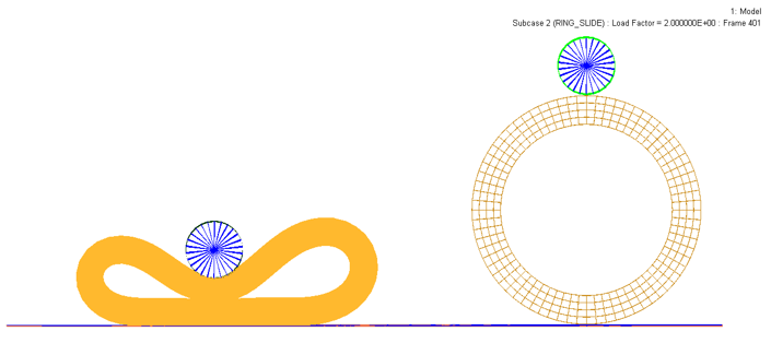
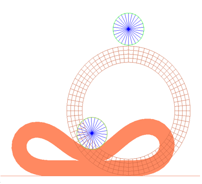
A deformed rubber ring resting on a flat, rigid surface. Another circular rigid roller rests at the top of the ring, and is in contact with the ring at just a point. Contact is defined between the rigid surfaces and the outside surface of the ring and self-contact is defined in the inside surface of the ring. The loading is applied in two steps – in the first step, the circular roller is pushed down enough to produce self-contact of the inside surface of the ring. In the second step, the roller is simultaneously translated and rotated such that the crushed ring rolls along the flat rigid surface producing a constantly changing region of contact. Here the nonlinear implicit analysis is run.
- Entity
- Element Type
- Rubber Ring
- Solid elements (1st order)
- Roller
- Shell elements (1st order)
- Flat Floor
- Shell elements (1st order)
- Young’s Modulus
- 210000 Nmm-2
- Poisson's Ratio
- 0.3
- Poisson's Ratio
- 0.495
- Material Model
- Arruda-Boyce
The hyperelastic material constants are obtained by conducting curve fitting with the provided TAB1 (simple tension/compression), TAB2 (biaxial tension), and TAB4 (shear) data for rubber material in the MATHE entry, during the OptiStruct run.
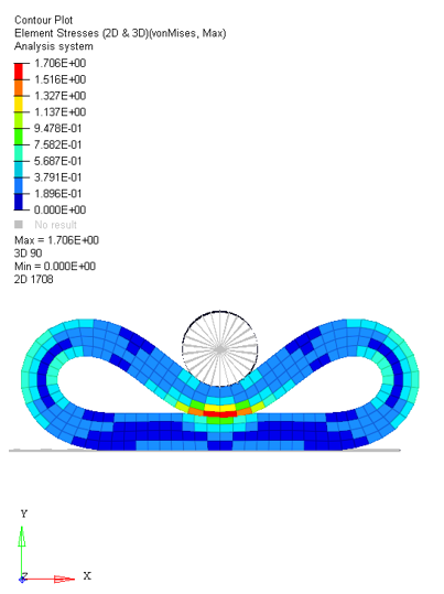
Results