OS-E: 0115 Finite Sliding Contact
Nonlinear Analysis with finite sliding contact between rack and pinion gears.
Model Files
Model Description
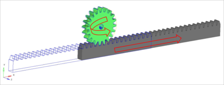
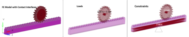
This example has only one nonlinear static load case where a rotation of 5 radians was applied to the pinion gear. The pinion gear engages with the rack using finite sliding contact causing the rack to move relative to the pinion, thereby translating the rotational motion of the pinion into linear motion.
The finite sliding contact between the rack and the pinion gears was defined with no friction and with surface to surface contact discretization.
There was also contact stabilization used to successfully solve the model. The default values on the CNTSTB Bulk Data card were used except for the S1 field, that is, scale factor for stabilization coefficient at the end of a subcase where a value of 1e-6 was used.
- FE Model
- Rack Gear
- Hexas and Pentas
- Pinion Gear
- Hexas and Pentas
- MAT1
- Young’s Modulus
- 2.1E5
- Poisson's Ratio
- 0.3
- Initial Density
- 7.85E-9
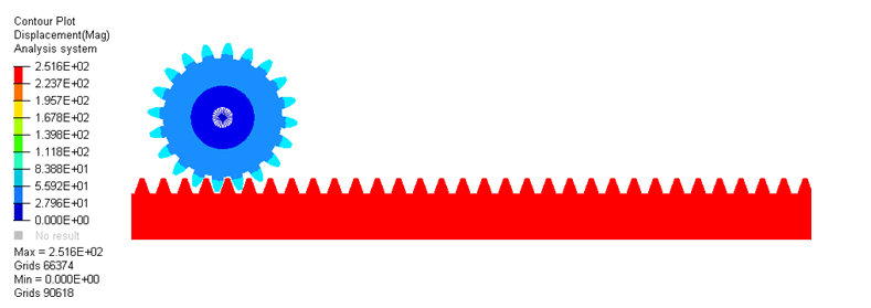
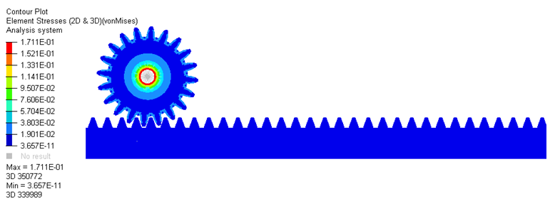
Results