OS-E: 0170 Revolute Joint Using JOINTG and MOTNJG
Demonstrate a revolute joint using JOINTG and MOTNJG. The JOINTG entry can be used for defining a variety of joints, including revolute, ball, universal, cardan, and so on. Motion on these joints can be applied using the MOTNJG entry.
Model Files
Model Description
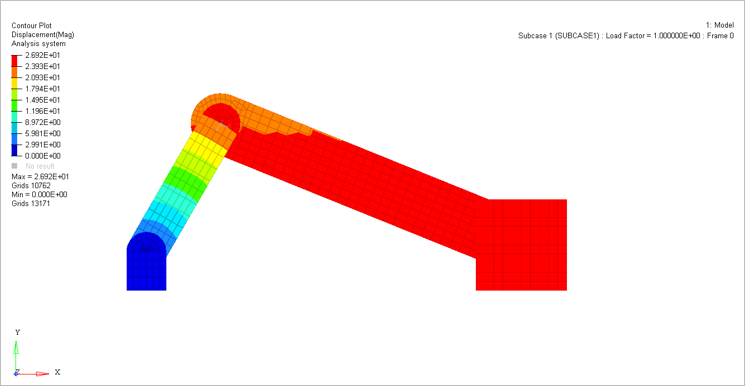
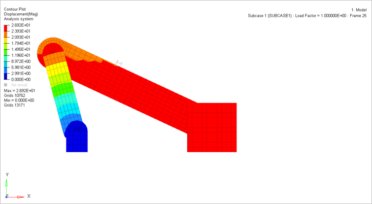
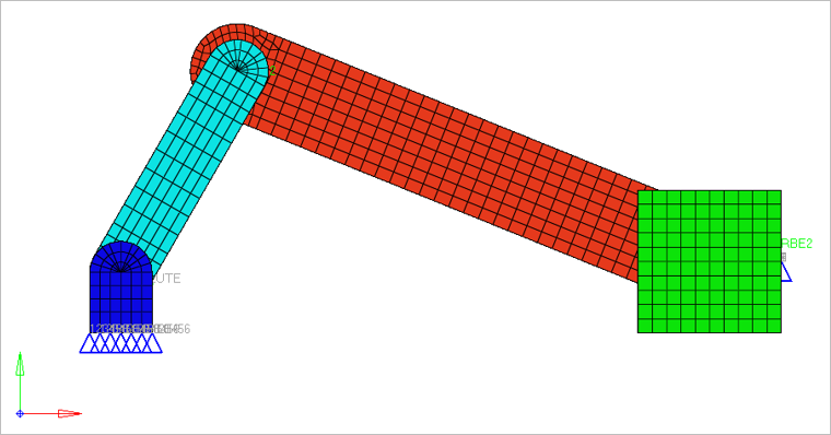
Objective here is to do conduct a Large Displacement Nonlinear Analysis of a Slider-Crank model using JOINTG. A horizontal enforced displacement is applied using an SPC entry on one end of the block in the negative X direction. The model is shown in Figure 1.
Twelve JOINTG entries are used in the model, to represent the six joints.
A revolute joint is a joint which allows single axis rotation functions (for example, in a door hinge). The joint works by allowing free rotation (or enforced displacement via MOTNJG) about one degree of freedom of the two grid points associated with the joint (the two selected degrees of freedom should be the same). The remaining rotational degrees of freedom are automatically constrained. The translational degrees of freedom can be fixed by defining an additional ball joint.
- JTYPE should be set to REVOLUTE.
- The X-axis of the coordinate system (CID1) of grid point 1 should be parallel (and in the same direction) to the X-axis of coordinate system (CID2) of grid point 2. The MOTNJG Subcase and Bulk Data Entries can be used to define the value of rotation (DOF=4) about the X-axis.
- The other axes of the coordinate system may point in any direction.
- The translational degrees of freedom can be fixed by defining an additional ball joint.
- FE Model
- Elements Types
- CHEXA
- MAT1
- Young’s Modulus
- 2.1E7 Pa
- Poisson's Ratio
- 0.3
Results