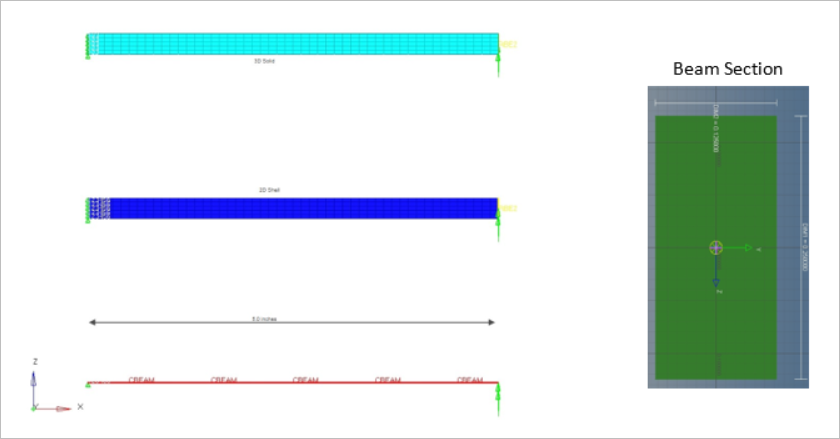
The beam cross-section is modeled as an idealized section to compare with the
assumptions of the analytical solution.
The loading is assumed to be applied through the centroid of the element
cross-section (the neutral axis). This model also has 2D Shell and 3D hexa beam for
comparison purpose only. The objective is to find the maximum magnitude of the
displacement of the cantilever beam undergoing moment load of 100 lb*in z-axis, as
shown in Figure 1.
The linear material properties are:
Young's Modulus
30E6 MPa
Poisson's Ratio
0.3
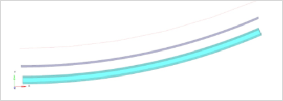
Results
Figure 2. Deformation
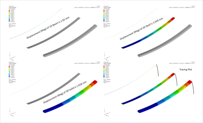
The plot of the deformations of the cantilever beams are shown in Figure 3. The cantilever behavior can be observed of different types of
beams (1D beam, 2D shells, 3D solids) solved for nonlinear large displacement
analysis.Figure 3. Displacement Contour