OS-E: 0180 3-Point Bending using RBODY
Demonstrates RBODY which is used in this nonlinear large displacement implicit analysis involving contacts using OptiStruct.

Model Files
Model Description
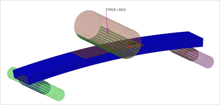
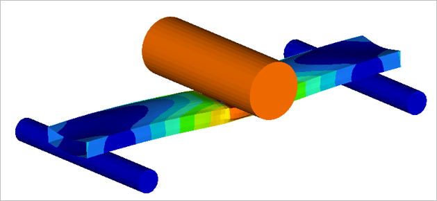
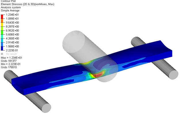
This model consists of a steel beam resting on two steel supports and crushed from the middle using another steel cylinder. Sliding contacts are defined between the cylinders and the steel beams. The cylinders are defined as RBODY and the centroid nodes are defined as the reference node, on which the load and boundary conditions can be applied. A load of 500N is applied on the centroid node (reference node) of the big cylinder, the big cylinder can move only in the x direction and the two small cylinders are constrained in all the DOFs. Here a nonlinear implicit analysis is run.
- FE Model
- Steel Beam and Cylinder
- First order shell elements
- Steel Beam and Cylinder
- Young's Modulus
- 210 GPa
- Poisson's Ratio
- 0.3
- Initial Density
- 7.9 x 10⁻⁶ kg/mm3
Results

