OS-E: 0135 Contacts and Pretensioning of Bolts
Nonlinear Static analysis involving contacts and pretensed bolts is demonstrated.
Model Files
Model Description
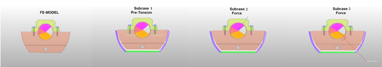
The model mimics a typical bolt pretension scenario in powertrain applications which could be followed by duty cycle loads.
- Case 1
- Nonlinear Static Analysis
- Bolt pretension
- Case 2
- Nonlinear Static Analysis
- Bearing (LOAD) as continuation load after (CNTNLSUB) pretension (STATSUB(PRETENS))
- Case 3
- Nonlinear Static Analysis
- Bearing (LOAD) as continuation load after (CNTNLSUB) pretension (STATSUB(PRETENS))
- FE Model
- Bolts and Ring
- CHEXA
- Flange
- CTETRA
Subcase 2 and 3 are both continued from the pretension subcase using the CNTNLSUB card.
- Contact Type 1
- Friction Contact
- Static Friction Coefficient = 0.3
- Components Involved
- Top and Bottom: Top and Bolt
- Contact Type 2
- PCONT Contact
- Static Friction Coefficient = 0.3
- Components Involved
- Top and Ring: Bottom and Ring
- Contact Type 3
- FREEZE Contact
- Components Involved
- Bottom and Bolt
- Steel for Bolts
- Values
- Young’s Modulus
- 2.08E5 MPa
- Poisson's Ratio
- 0.3
- Density
- 7.8E-9 ton/mm3
- Aluminum for Flanges
- Values
- Young’s Modulus
- 7.4E4 MPa
- Poisson's Ratio
- 0.33
- Density
- 2.6E-9 ton/mm3
- Bronze for Ring
- Values
- Young’s Modulus
- 1.22E5 MPa
- Poisson's Ratio
- 0.35
- Density
- 8.8E-9 ton/mm3
Results
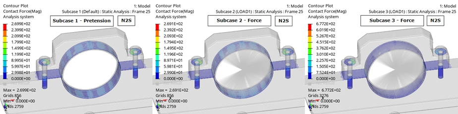
The displacement results for bolts in Subcase 1 are presented in Figure 2. Bolt total forces in different subcases can be extracted from .pret file. In Figure 2, observe the displacement result snapshots from all three subcases.
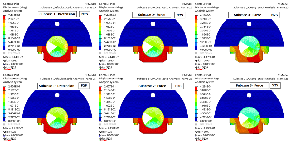
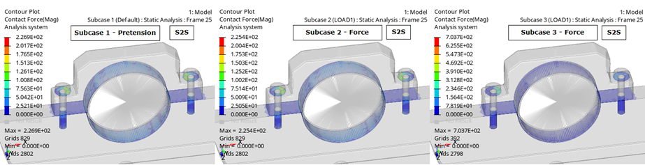
The second run of this model was done with all Node to Surface (N2S) contacts. You can change the DISCRET field of all CONTACT entries with N2S and rerun the model to generate the N2S model results. An N2S discretization generally leads to quicker convergence and you can read the .out file of both the runs for finding out the time taken to run the simulation. In this case, the S2S run was 1.6x slower than the N2S run on the same machine. However, S2S contact discretization provides more accurate results in most cases.