Create Surfaces from FE
Use the Surfaces: From FE tool to create surfaces that closely fit a selection of shell elements.
-
From the 2D ribbon, click the tool.
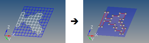
Figure 2. 
-
Click
 on the guide bar and define
the following options:
on the guide bar and define
the following options:
- Surface Complexity
- Affects how many surfaces are created. This option takes into account a number of factors, including the boundary shape of the area to be surfaces as well as its topology. Higher complexity values create a smaller number of more complex surfaces, but require longer calculation times to create those surfaces. Smaller values produce a larger number of smaller, simpler surfaces, but do so more rapidly.
- Tolerance
- Choose a method to determine how closely the new surfaces adhere to the underlying elements. The tolerance value is the maximum distance by which the surface created differs from the selected elements at any location. This is particularly important for curved meshes.
- Select the source shell elements used to generate surfaces.
-
Choose a method for selecting features (surface edges).
By default, features are automatically determined. Uncheck Auto sharp features to manually specify 1D plot elements (features).
1D plot elements must be selected to represent the edges of the surfaces to be created. It is recommended to select a closed loop of plot elements in order to best guide the algorithm. Features can be created using the Features tool.
The algorithm used by this function tries to subdivide shell elements into subsets if it does not succeed in creating a single surface through the selected shell elements.
-
Define the following:
- Split by comp components
- Maintain boundaries between adjacent components, so that a single mesh plane will still produce separate surfaces based on the components that the elements belong to.
- Associate nodes
- Ensure that the mesh nodes are associated to the new corresponding surfaces. This allows re-meshing of the surface to replace the original mesh instead of creating a new overlaid mesh.
-
On the guide bar, complete one of the following:
- Click
 to apply and stay in the tool.
 - Click
 to apply and close the tool.
 - Click
 to exit the tool without applying.
- Click