FW-H Input Definition
The purpose of the FW-H tool within the HyperMesh CFD Post-Processing environment is to define the input definition for the FW-H noise propagation methodology, allowing you to predict the sound pressure level at a farfield microphone locations. To define the propagation problem, you will identify one or more acoustic sources that emit sound to the far-field, microphone locations, global properties and the output data configuration. The tool will generate the associated input files to be run external to HMCFD, using the FW-H calculation tool provided in HWCFDSolvers (uFx, Linux distribution).
The calculation definition is defined in five sections within the FW-H Aeroacoustics tool.
-
From the Post ribbon, Aeroacoustics section, click the FW-H icon.
Figure 1. 
-
Define the FW-H input configuration within the following five sub-sections of
the context.
Figure 2. 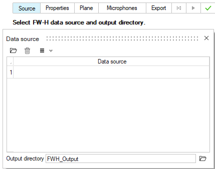
-
Define the data source.
-
Load the data file of interest into the tool using the file browser
icon
 or current data set selection icon
  .
.
The source file is defined as the solver generated output file that is sampled in the volume field via a monitoring surface (porous formulation). The data generated by ultraFluidX is read by the FW-H tool from the respective output folders. One or more files can be selected to define the acoustic source. The output folder that is generated and/or written to by the FW-H solver is defined by the Output directory.Figure 3. 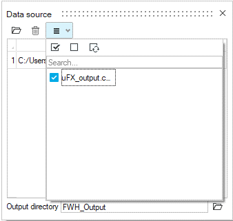
-
Load the data file of interest into the tool using the file browser
icon
-
Define the air properties. These are identical to uFX solver settings.
Figure 4. 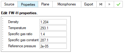
-
Add a reflection plane with acoustic absorption.
Up to three (one in each direction) can be defined by specifying the plane position and absorption coefficient. Indicates an absorption value for the plane:
- Fully rigid plane: absorption = 0
- Grass: absorption ≈ 0.6
- Fully absorbing material: absorption = 1
Figure 5. 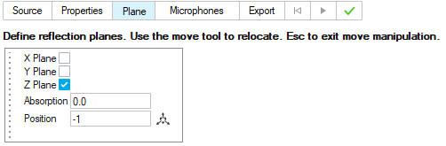
-
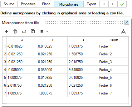
Define microphone locations.
-
The far-field microphone locations are defined by providing a set of
cartesian coordinates and associated name for each microphone. The
coordinates may be defined by selecting positions within the graphical
area associated with entities loaded into the session or by opening a
file containing x, y, z coordinate positions and probe names of the
microphones.
-
Export to the FW-H solver input file.
- Assign the export file name and location.
- If necessary, the Absolute path flag can be activated to write the file location along with the file name within the .xml file.
Upon export, the tool will write the .xml file and the microphone locations file in .csv format to the specified location where the .xml file is written.Figure 6. 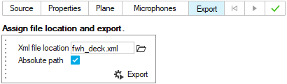
-
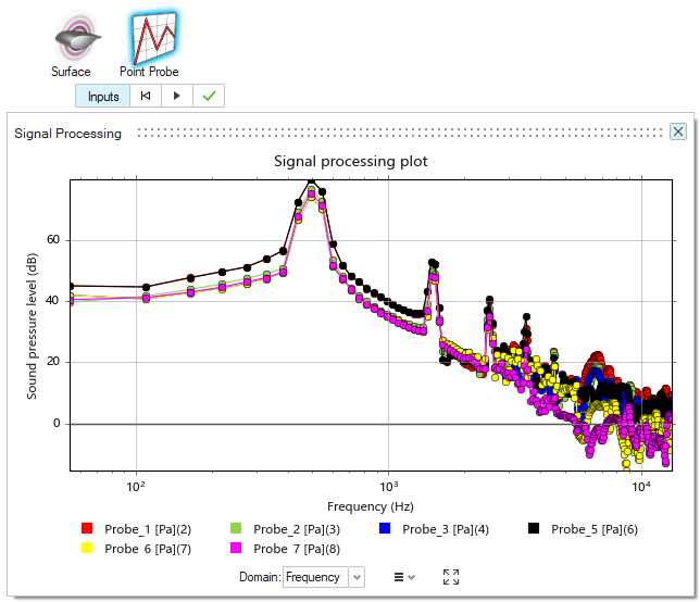
Once the FW-H Solver has completed, the file name in the output folder will be
followed by one of two tags, sync or
notsync. The sync tag refers to
signals using a global reference time and contain leading or trailing zeros
(i.e., times when no signal is recorded at the respective receiver).
notsync refers to signals using a local reference time,
containing only the usable part of each receiver's signal. The desired file may
then be loaded into for a review of the computed outputs.
Figure 7.