
Calculate Engineering Quantities
Use the Engineering Quantities tool to simplify the calculation of values that are commonly used during the post-processing of CFD results.
For example, the calculation of pressure drop between two surfaces in the model can be computed by selecting Difference on the horizontal guide bar, then choosing the first collection of surfaces over which to average the pressure, then selecting the second group of surfaces over which to average the pressure. HyperMesh CFD Post automatically computes the area average of the selected variable (in this case pressure) across all surfaces of each selection group, then computes the difference between the two integrated values. The difference is computed by subtracting the value of the second selection group from the value of the first selection group. The resulting values are displayed in a table that updates upon change of time step. If one of the selection groups is derived geometry (such as a slice plane), the engineering quantity output is also updated upon modification. The table that displays the engineering quantity output can be displayed once the value is computed, outside of the edit context. This is controlled by toggling the visibility on and off in the browser. The values computed by the Engineering Quantities tool will be updated upon the change of time-step.
-
From the Post ribbon, click the Engineering Quantities
tool.
Figure 1. 
-
Use the drop-down on the guide bar to select an
engineering quantity of interest.
Figure 2. 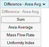
The Engineering Quantities tool supports the following operations: Sum, Difference, Surface Statistics, Mass flow rate, Uniformity Index and Force.
- Sum can be used to compute the area weighted sum of a variable on an entity. For example, if the wall shear stress is an output field from the solver, the sum over a surface will yield the viscous force on that surface.
- Difference can be used to compute the difference of a given variable for two similar entities. For example, compute the pressure difference of a slice plane upstream of an object from a slice plane downstream of an object.
- The surface statistics option yields the area average, minimum,
maximum and standard deviation of a variable for the requested
selection. The area average is weighted by the individual surface
elements that make up the selection, providing the area weighted
integral of that collection of elements, similarly for the standard
deviation. The minimum/maximum location of the field is displayed in
the graphical window, with a blue sphere representing the minimum
and a red sphere representing the maximum. Additionally, the
geometric value for Area, X/Y/Z min : max locations are provided
within the table.
Figure 3. 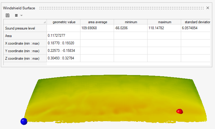
- The mass flow rate option provides the ability to compute the mass flow rate through a surface based on a velocity vector and a density field (or constant value).
- The uniformity index option computes the amount of local variation from the area average value of the specified variable on an entity normalized by the area average of that entity.
- The total force acting on a surface can be computed by integrating
the contributions from pressure and wall shear stress for each
element on a collection of surfaces. The expected result is a vector
(length of 3) to describe the force in the 3 Cartesian directions.
The force calculation in 1 direction x is described as:
- where F is the force, P is the pressure, n is the normal vector, Sx is the wall shear stress in the x direction, and A is the area for a given surface element. The integral of the force is computed to provide the total force acting on the collection of surfaces, for each direction.
- By default, the force calculation will use the time-average pressure and wall shear stress if available, reverting to the instantaneous values if not.
-
Select surfaces, boundary groups, or slice planes to consider and define the
variable/parameters in the microdialog to proceed.
Some engineering quantities require only a single selection group, such as uniformity index, mass flow rate, sum, and average. Some quantities, such as difference, require multiple inputs to calculate the resulting value.
For mass flow rate, an input velocity vector is required, as well as the definition of a density field. The density can be specified as a constant through the microdialog or an existing scalar field can be used to specify the density.
-
The force calculation includes Optional parameters to
provide the sectional force or normalize it according to user input.
- The normalization is computed by dividing each force component by the dynamic pressure (0.5*rho*vel^2*Area).
- The sectional force can be computed when requested. When Sectional force
is turned on, the Engineering Quantities tool will return the force
vector as a function of the three Cartesian direction for the total
number of Sections. These values are available for two-dimensional
plotting.
Figure 4. 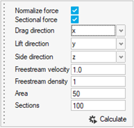
- Click Calculate.
- Optional:
Click
 in the results dialog to save the values.
-
On the guide bar, click one of the following:
 - Save changes and remain in the tool
 - Save changes and exit the tool
Tip: Engineering Quantities may be stored for future use or reporting from the browser by selecting the quantity of interest, or >