Since version 2026, Flux 3D and Flux PEEC are no longer available.
Please use SimLab to create a new 3D project or to import an existing Flux 3D project.
Please use SimLab to create a new PEEC project (not possible to import an existing Flux PEEC project).
/!\ Documentation updates are in progress – some mentions of 3D may still appear.
Mapped mesh generator
Définition
This mesh generator allows one to mesh :
- the rectangular faces in rectangles (or quadrangular elements)
- parallelepiped volumes in « bricks » (hexahedral elements)
The contour of a face is divided into four lines, each one meshed so that two opposite lines have the same number of elements. The surface to be meshed is topologically equivalent to a rectangle. For the mapped mesh of a volume, the volume is topologically equivalent to a parallelepiped form.
The user has full control over the number and the quality of the elements.
Illustration
The meshing of a face and of a volume by means of a mapped mesh generator is illustrated in the figure below.

|

|

|

|
| Rectangle, Quadrangle |
“Brick”, Hexahedron |
||

Use
This mesh generator is particularly useful to mesh thin regions (air gaps, thin laminations, skin depth).
It permits the reduction of mesh disturbance effects (noise) on results by using the symmetries of the device.
It is economic (reduction of the number of nodes).
Limitation
This mesh generator takes longer and more difficult to implement than the automatic mesh generator.
3D specificity
The mapped mesh generator for volumes is less powerful than the mapped mesh generator for faces. The geometry of the volume to be meshed must be close to the geometry of a cube in order that the mesh quality be good.
Note that a degradation of the mesh can be observed in cylindrical volumes. The mapped mesh generator does not accept volumes having cylindrical faces of 180 degrees or more. If the elements are too fine, the mesh may become unusable for the computational process.
2D Examples
Examples of faces meshed with the mapped mesh generator are presented below.
| Mapped meshing of 4-line faces | |
|---|---|

|
The first face is a quadrilateral. The top and bottom lines are geometrically meshed and the mesh is perfectly propagated inside of the face. |

|
The second face is a 180-degree piece of ring. A geometric line subdivision is used in the radial direction. The mesh is perfectly propagated inside of the face. |
| Mapped meshing of 5 or more-line faces | |
|---|---|

|
The face shown below is composed of twelve lines and points. It is characterized by significant concavities. The structure is formed using the four end points on the left and on the right. The other eight points are angular. The resulting mesh is incorrect. To obtain a valid mesh, this face should be subdivided, e.g., into five faces. |

|
Two examples of mapped mesh of a concave face bordered by six lines. Depending on the mesh discretization, the mesh will be correct or not. Subdivision of the face into two faces is recommended to insure a quality mesh. |
3D example
Some examples of volumes meshed with the mapped mesh generator are presented below.
| Volume meshed with the mapped mesh generator | |
|---|---|

|
Mapped mesh of a hexahedron with planar faces: the elements are of good quality. |

|
The mesh of the first tile is not perfect, but the deformation of the elements stays within acceptable limits, so the mesh is correct. |
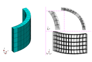
|
The second tile is thinner. It has a thinner mesh across the volume. The elements are very distorted and most of the elements that touch the internal face are not correct. To obtain a correct hexahedral mesh, one can either sub-cut the volume, or, (preferable for this geometry), use an extrusive geometric mesh generator with a mapped base. |