Since version 2026, Flux 3D and Flux PEEC are no longer available.
Please use SimLab to create a new 3D project or to import an existing Flux 3D project.
Please use SimLab to create a new PEEC project (not possible to import an existing Flux PEEC project).
/!\ Documentation updates are in progress – some mentions of 3D may still appear.
Laminated magnetic non conducting regions
Introduction
Laminated magnetic non conducting regions are regions dedicated to the representation of stacks of insulated electrical steel sheets in a Flux project. This chapter discusses the following aspects related to this kind of region:
- What this type of region models;
- How to create this region in a Flux project;
- Limitations;
- Evaluation of iron losses on laminated magnetic non conducting regions.
What this type of region models
Laminated magnetic non conducting regions are usually employed to represent magnetic cores composed by the association of multiple sheets of an electrical steel in a stack, such as the stator and rotor of electrical machinery. Stacks of lamination steel are also used in transformers, actuators or in any part of a magnetic device that could be subjected to eddy currents. The purpose of the stacking is to shorten the available paths for eddy currents when compared to a bulk magnetic core, leading to reduced losses.
- the region is classified as non conducting because it cannot have an imposed or induced current density. This is ensured at the Finite Element model level and is true for all Flux applications, even if the user assigns a material with an electrical conductivity (i.e., with an electrical J(E) property) to such a region.
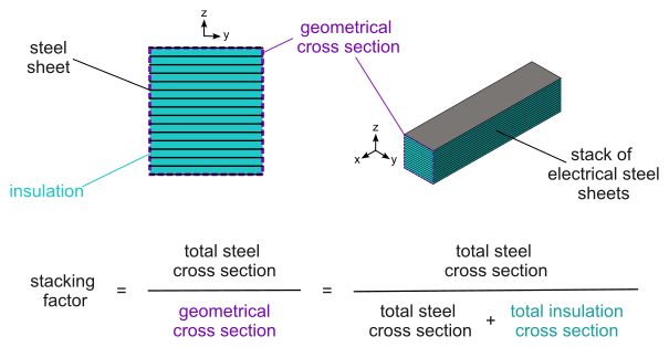
- the region is said to be laminated because it automatically accounts for the effect of the insulation of the electrical steel and for the small air gaps between the sheets in a stack. This is achieved through a homogenization procedure implemented in Flux. The overall effect of this homogenization is that the effective cross-section of magnetic material available for the magnetic flux to traverse in the region is reduced. The reduction factor is known as the stacking factor of the region, and corresponds to the total cross section area occupied by magnetic material (steel) in the stack divided by the surface area of the geometrical cross section of the same stack (i.e., the total cross section area, including the insulation and air gaps between sheets). This definition is illustrated in Figure 1 below.
Finally, laminated magnetic non conducting regions may be used to study the iron losses developed in magnetic cores. Even if this kind of region can not yet account for hysteresis during solving, it is compatible with à posteriori methods for the evaluation of iron losses. Further details are available in section Evaluating iron losses on laminated magnetic non conducting regions below.
How to create this region in a Flux project
In Flux 2D and in Flux Skew, laminated magnetic non conducting regions are surface regions, while in Flux 3D they become volume regions. They are available in all magnetic applications (i.e., Magneto-static, Steady State AC and Transient), but not for Flux 2D axisymmetric computations, because the hypothesis on the magnetic field direction can not be satisfied for this type of domain.
In any case, this region may be created as follows:
- while in pre-processing, start the creation of a new surface region (2D, Skew) or of a new volume region (3D) through options available in the Physics menu or by right-clicking the region type in the Data tree;
- then, in the New Surface Region (2D, Skew) or in New Volume Region (3D) dialog box, select Laminated magnetic non conducting region from the Type of region drop-down menu;
- provide the following inputs:
- the material associated to this region using the Sheet material drop-down menu;
- the Stacking factor of the region, a dimensionless number between 0 and 1, whose typical values are greater than 0.95. In case the user indicates a stacking factor lower than 0.5, a warning message is prompted to inform that the configuration is unusual.
- For Planar sheets:
- a Coordinate System and
- the three components of a Direction vector normal to sheets (i.e., orthogonal to the lamination plane), expressed in the selected system of coordinates.
- For Cylindrical sheets:
- a Coordinate System;
- the three coordinates of a Point on the cylinder axis, expressed in the selected system of coordinates and
- the three components of a Direction vector of the cylinder axis, expressed in the selected system of coordinates.
- The material assigned to the laminated region must have a magnetic B(H) property of type Isotropic analytic saturation + knee adjustment and also a B(Stress) magneto-mechanical property fully described.
- The Mechanical stress dependency option must be enabled during the creation of the region, and the mechanical stress dependency model of the region must be fully described.
Limitations
- Flux 2D axisymmetric applications;
- materials with B(H) hysteretic properties:
- materials with B(H) properties normally used to represent magnets;
- materials with B(H) properties described by anisotropic laws.
Evaluating iron losses on laminated magnetic non conducting regions
Laminated magnetic non conducting regions are conceived in Flux to work with à posteriori methods for the evaluation of iron losses. The approaches implemented in the software are available while in post-processing through the Computation menu (Computation → Computation of iron losses) and are:
- the modified Bertotti model and
- the Loss Surface (LS) model.
For a comprehensive discussion on how to evaluate iron losses à posteriori in Flux, the user is referred to the following user guide chapter: Evaluating iron losses à posteriori in magnetic cores.
Further reading
- Magnetic cores in Flux
- B(Stress) magneto-mechanical model: dependency between B(H) constitutive law and mechanical stress
- Evaluating iron losses à posteriori in magnetic cores
- Evaluating iron losses à priori in magnetic cores
- Isotropic soft magnetic material: hysteresis Preisach models
- Isotropic soft magnetic material: hysteresis Jiles-Atherton model