Since version 2026, Flux 3D and Flux PEEC are no longer available.
Please use SimLab to create a new 3D project or to import an existing Flux 3D project.
Please use SimLab to create a new PEEC project (not possible to import an existing Flux PEEC project).
/!\ Documentation updates are in progress – some mentions of 3D may still appear.
Link regions and components: coil conductor
Link regions and components
To link the regions of the coil conductor type (of the FE domain) to the components of the stranded coil conductor type (of the electric circuit), follow the next procedure:
| Step | Action |
|---|---|
| 1 |
In the Physics menu:
|
| → | Division of graphic zone in two and visualization of FE domain in one
zone and the electric circuit in the other Display of the face regions of coil conductor type in the form of array |
| 2 |
In the array*, fill out the zones for each region:
|
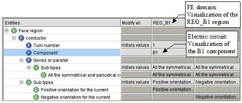
Array of coil conductors
The array corresponding to the regions of the coil conductor type (2D) is presented in the figure below.
In this array, the zones which allow the visualization of the regions (of coil conductor type) and of the electric components (of stranded coil conductor type) are showed in the figure below.