Electric Motor Component
Description
The electric motor duty cycle defines the load cycle that the motor would experience during its operation. This temperature-driven cycle determines if the motor is suitable for its task or requires additional cooling or other changes.
A duty cycle defines a motor’s operational load, including the start/stop frequency, braking, and load variations.
The Flow Simulator electric motor component is designed for integrated duty cycle analysis with Altair's FluxMotor, streamlining user input and results processing. It requires FluxMotor and is not for standalone use.
Quick Guide for the Electric Motor Component in the User Interface

- An EMC does not have a chamber association. You can drag-and-drop it from
the Element Library.
Figure 2. 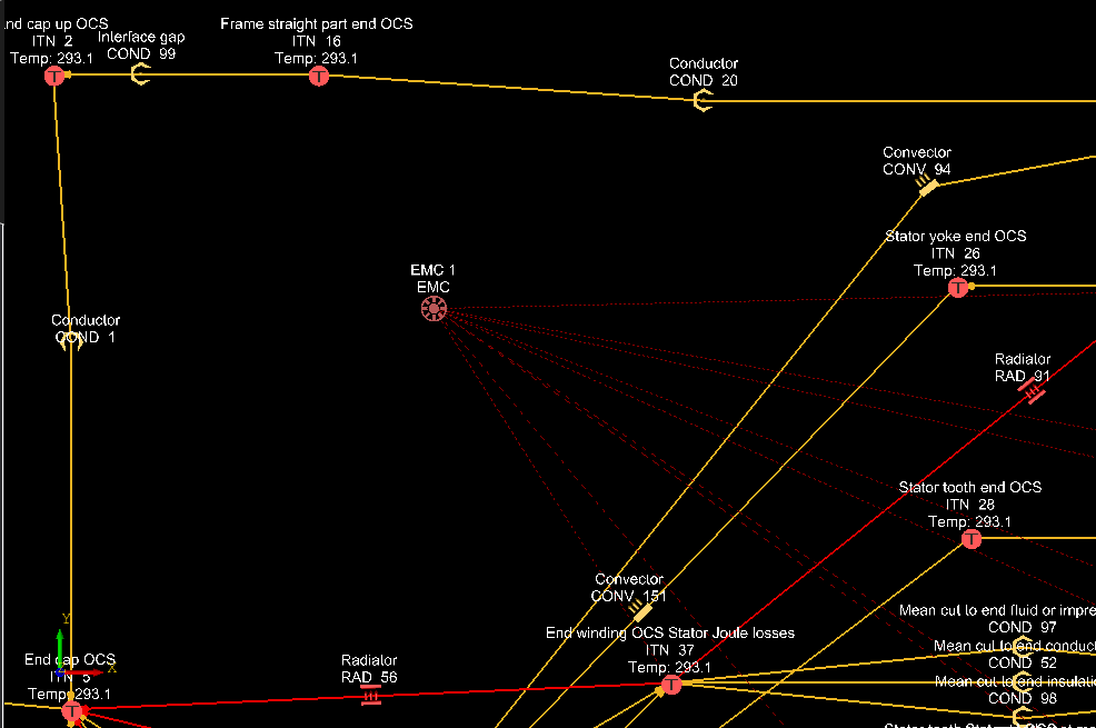
- Use Browse to select a loss file for the duty cycle. The Loss File Full Path is automatically filled.
- The Losses section defines the set of thermal nodes
associated with each part of an Electric Motor, which contribute to the
losses in the duty cycle. This topic refers to each part of the Electric
Motor as a Loss type. “Loss” refers to inefficiencies in the electric motor
that result in heat generation. The heat generated is applied to the thermal
nodes in the Flow Simulator model.
Figure 3. 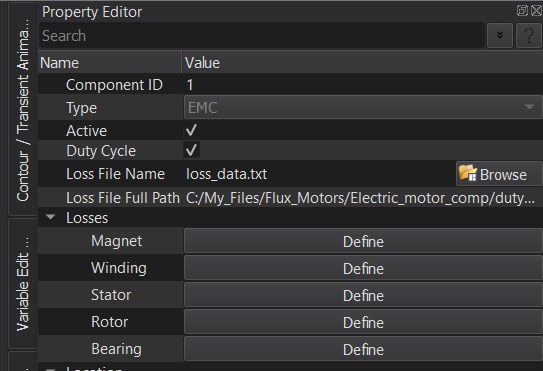

- Use Select from View to select the thermal nodes
manually from the model or give a range of Thermal Node IDs using "+". If
you use “+”, then the following dialog is displayed:
Figure 5. 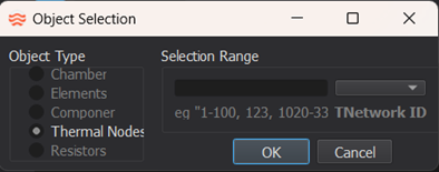
From the Object Selection dialog, Thermal Node is the only available option.
Use "," to select the item ID or use "-" to define a range.
- Use Add Tnode to individually define the Thermal Node IDs.
- Loss Scale defines the geometric dependance of the loss that has been calculated in each node of any part of the electric motor. This must be user-provided. The default is 1.
Electric Motor Component Inputs
| Index | UI Name (.flo label) | Description |
|---|---|---|
| 1 | Duty Cycle (DUTY_CYCLE) |
TRUE: Turns on the Duty Cycle calculation. FALSE: Turns off the Duty Cycle calculation. Use this mode for post-processing, which is planned for a future release, Default: TRUE |
| 2 | Loss File Name (DUTY_CYCLE_FILE_NAME) |
Use Browse to select the loss file for
the Duty Cycle Calculation. Displays the loss file name. |
| 3 | Loss File Full Path (DUTY_CYCLE_FILE_FULL_PATH) |
Automatically populated. This displays the full path to the loss file for the duty cycle calculation. |
| 4 | DUTY_CYCLE_FILE_REL_PATH | Only in the .flo file; automatically populated. This path is used first when Flow Simulator loads the loss file for the duty cycle calculation. If it fails to load, the full path is used. |
| 5 | Losses (Not in the .flo file) |
This section lists all parts of the electric motor, which
participate in the loss calculation in duty cycle:
|
| 6 | (MAGNET_NODES) |
Use this to define which nodes are designated as “Magnet“ in the electric motor they are analyzing. |
| 7 | (MAGNET_LENGTH_SCALES) |
Defines the geometric dependance of the “Magnet” loss that
has been calculated in each node of any part of the electric
motor. Default: 1.0. |
| 8 | (WINDING_NODES) |
Use this to define which nodes are designated as “Winding“ in the electric motor they are analyzing. |
| 9 | (WINDING_LENGTH_SCALES) |
Defines the geometric dependance of the “Winding” loss that
has been calculated in each node of any part of the electric
motor. Default: 1.0. |
| 10 | (STATOR_NODES) |
Use this to define which nodes are designated as “Stator“ in the electric motor they are analyzing. |
| 11 | (STATOR_LENGTH_SCALES) |
Defines the geometric dependance of the “Stator” loss that
has been calculated in each node of any part of the electric
motor. Default: 1.0. |
| 12 | (ROTOR_NODES) |
Use this to define which nodes are designated as “Rotor “ in the electric motor they are analyzing. |
| 13 | (ROTOR_LENGTH_SCALES) |
Defines the geometric dependance of the “Rotor” loss that has
been calculated in each node of any part of the electric motor.
Default: 1.0. |
| 14 | (BEARING_NODES) |
Use this to define which nodes are designated as “Bearing“ in the electric motor they are analyzing. |
| 15 | (BEARING_LENGTH_SCALES) |
Defines the geometric dependance of the “Bearing” loss that
has been calculated in each node of any part of the electric
motor. Default: 1.0. |
Electric Motor Component Duty Cycle Calculations
- Loss File
- The Loss file contains tables of losses for each part (loss type) of the electric motor that is being analyzed. FluxMotor creates the file as part of the duty cycle analysis.
-
Figure 6. 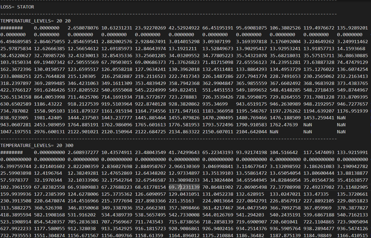
- The rest of the table includes losses corresponding to the speed and
torque defined at that temperature level. Unit: W.
Figure 7. 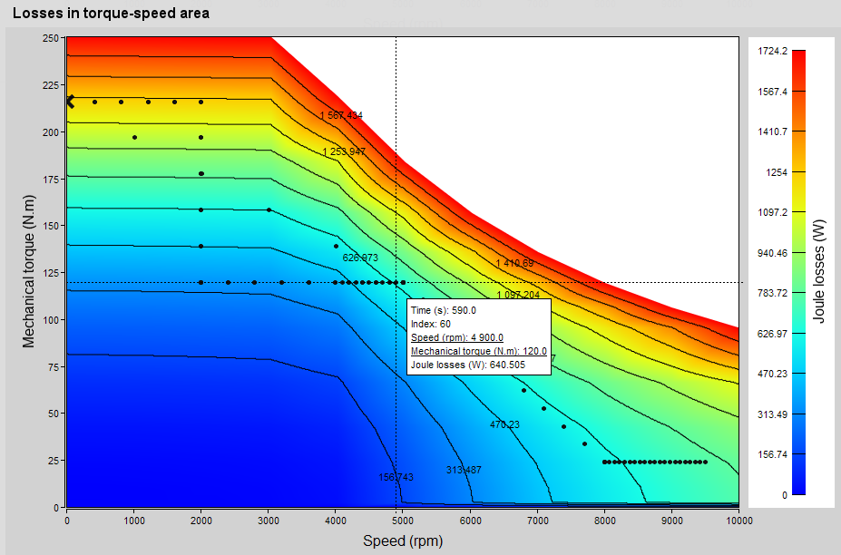
- Duty Cycle Operational Load Definition
- The operational load for the duty cycle is defined as a
Mission in Flow Simulator. Use :
Figure 8. 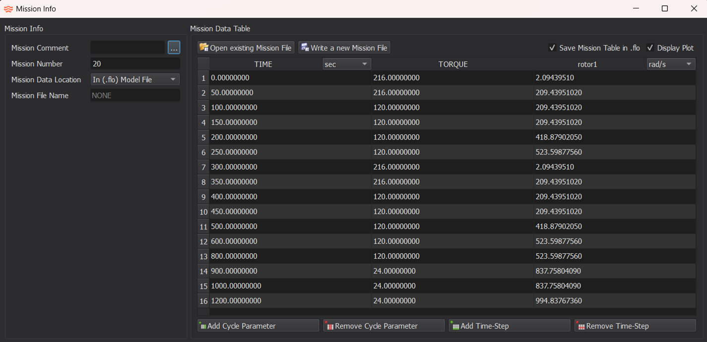
- The SPEED operational load column can be
user-defined (rotor1 in this case). This is
specified in under as shown below:
Figure 9. 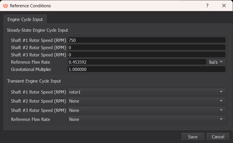
- The mission table contains a “Mission Number”, which is selected in .
Figure 10. 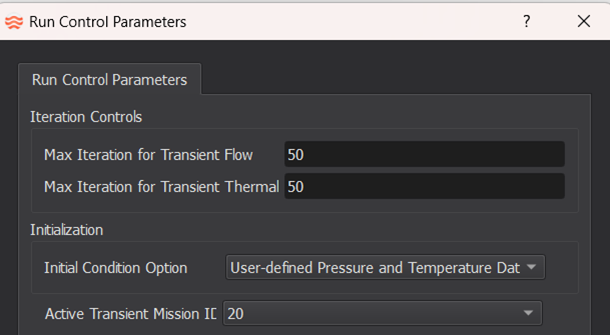
- Calculate Losses
- The calculation requires two steps:
- Each time step:
For each loss type (Magnet, Stator, and so on), a table of interpolated loss values is created for each temperature level for the speed and torque given in the mission table, corresponding to that time step using bilinear interpolation. This is created at the start of each time step and is used for all internal thermal iterations of that time step.
- For each internal thermal iteration:
- Find the average temperature for magnet nodes and winding nodes from the thermal analysis of the motor.
- Use the table of interpolated loss values, created at the start of the time step, to perform bilinear interpolation for the average magnet and winding temperature for each loss type.
- Multiply the geometric dependance of the nodes (as defined in Loss Scale for a loss type) to the loss calculated for each loss type. This provides the individual losses to be applied to each node of a loss type (Magnet, Stator, and so on).
- Apply the losses to each node for further thermal analysis.
- Each time step:
Electric Motor Component Outputs
| Name | Description | Units |
|---|---|---|
| ELECTRIC MOTOR COMPONENT | The component ID. | (number) |
| SPEED | The speed calculated using interpolation for the current Time as provided in the mission table. | Revolutions/minute |
| TORQUE | The torque calculated using interpolation for the current Time as provided in the mission table. | Ft-lb, N-m |
| AVERAGE MAGNET TEMPERATURE | The calculated Magnet temperature averaged over all Magnet nodes for the current time step. | °K, °F |
| AVERAGE WINDING TEMPERATURE | The calculated Winding temperature averaged over all the Winding nodes for the current time step. | °K, °F |
| LOSS | The name of the loss type for the results. The subsequent
results are for this loss type, until we see a different
Loss type listed. All five Loss types are listed in each EMC result section. |
No units Character string |
| TNODE | This column of the result table specifies the thermal node
IDs, which were defined for each loss type. Displayed under the LOSS section for each loss type and is defined for all five loss types. |
number |
| TT | This column of the result table specifies the temperature
reached by each thermal node during the current time
step. Displayed under the LOSS section for each loss type and is defined for the five loss types. |
°K, °F |
| NODAL_HEAT | This column of the result table specifies the loss calculated
in each thermal node in the current time step. Displayed under the LOSS section for each loss type and is defined for the five loss types. |
BTU/s, W |
| AVG TEMPERATURE | The temperature averaged over all nodes for every loss type
for the current time step. Displayed under the LOSS section for each loss type and is defined for the five loss types. |
°K, °F |
| TOTAL LOSS | The sum of losses in each node of a loss type. This displays
the total loss from a given part, such as Magnet, Stator, and so
on, of an electric motor. Displayed under the LOSS section for each loss type and is defined for the five loss types. |
BTU/s, W |