Tank Components
Tank Component General Description and Quick Guide for Creation in the GUI
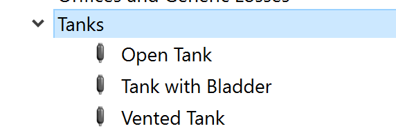
There are three tank subtypes available in Flow Simulator under “Incompressible Liquid Elements” section. Each is solved in a similar manner with the only major difference being how the pressure in the tank is determined. It is assumed that each tank is partially filled with a liquid and a gas fills the remainder of the tank.
The tank was developed for transient analysis, but it can be used in a steady state analysis. For a steady state analysis to converge, the model must be setup so the time derivatives in the following equations are 0 (dx/dt=0). For instance, all the liquid exiting the tank must also enter the tank.
Tank Component Inputs
Table of the inputs for the Tank Component.
| Element Specific Tank Component Input Variables | ||
| Index | UI Name (. flo label) | Description |
| 1 | Type (CPTYPE) | Type of component. See common component inputs table above for a full list. |
| 2 | Subtype (SUBTYPE) |
|
| 3 | CHAM1 | Primary Chamber that represents the liquid in the tank. Used for all 3 subtypes. Attachment point in the GUI for this chamber is near the bottom of the tank. |
| 4 | CHAM2 | Secondary Chamber that represents the gas in the tank. Only used for subtype 3 “Vented Tank”. Attachment point in the GUI for this chamber is near the top of the tank. |
| 5 | Geometry Type (GEOM_TYPE) |
Type of geometry inputs. For Fixed Geometry the cross section is constant for the entire height of the tank.
For Variable Geometry the cross section can change versus height of the tank.
|
| 6 | Tank Volume (TOTAL_VOLUME) | The tank volume for Geometry Type = 3 or 4 |
| 7 | Tank Diameter (DIAMETER) | The tank diameter for Geometry Type = 1 |
| 8 | Tank Cross-Section Area (CS_AREA) | The tank cross section area for Geometry Type = 2 |
| 9 | Tank Height (TOP_HEIGHT) | The tank height for Geometry Type = 1, 2, or 3 |
| 10 | Base Level Elevation (BASE_LVL) | Elevation at the bottom (base) of the tank. Used for pressure change due to gravity. |
| 11 | Initial Liquid Height (INIT_SURF_HT) | Height of the liquid in the tank at the start of the analysis. The height or the volume can be entered for the initial liquid in the tank. |
| 12 | Initial Fluid Volume (INIT_FLUID_VOL) | Volume of the liquid in the tank at the start of the analysis. The height or the volume can be entered for the initial liquid in the tank. |
| 13 | Gravity Multiplier (GRAV_MULT) | Multiplier on the constant for acceleration due to gravity, Gc. |
| 14 | Gas Separation Factor (GAS_SEPARAT) | The fraction of the gas that will separate from the liquid if a gas/liquid fluid is entering the tank. 0=no gas separation; 1=all gas will separate (gas will go to the gas “side” of the tank). |
| 15 | Thermodynamic Process Type, Side 1 (GAS_PROC_TYPE1) |
Gas expansion or contraction treatment.
|
| 16 | Poly Index (Outflow), Side 1 (POLY_EXP1) | Polytropic Index for expanding gas. Thermodynamic Process Type = 0 |
| 17 | Poly Index (Inflow), Side 1 (POLY_COMP1) | Polytropic Index for contracting gas. Thermodynamic Process Type = 0 |
| 18 | Initial Liquid (HTVOLFLAG) |
Initial Liquid 0: Height 1: Volume |
| 19 | Thermodynamic Process Type, Side 2 (GAS_PROC_TYPE2) | Similar to the side 1 input. The side 1 and 2 inputs are used depending on the tank subtype. |
| 20 | Poly Index (Outflow), Side 2 (POLY_EXP2) | Similar to the side 1 input. |
| 21 | Poly Index (Inflow), Side 2 (POLY_COMP2) | Similar to the side 1 input. |
| 22 | (NUMROWS) | Number of rows information for table |
| Table | Table of Port Information (PORT_ELEM) | Table of the elements that are attached to the tank and the height above the bottom of the tank of the attachment point. |
| Table | Table of Height vs Diameter (PORT_HEIGHT) | The table of tank height and diameter for Geometry Type = 11 |
| Table | Table of Height vs Diameter (PORT_CS_AREA) | The table of tank height and cross section area for Geometry Type = 12 |
| Table | Table of Height vs Diameter (PORT_VOLUME) | The table of tank height and volume for Geometry Type = 13 |
Tank Component Theory Manual
This section contains a preliminary derivation of how mass flow rate varies with time for simplified tank models.
Mass conservation:
For the open tank and the tank with a bladder the only ![]() and
and
![]() are the liquid
elements entering and leaving the tank. For the tank with a vent the
are the liquid
elements entering and leaving the tank. For the tank with a vent the ![]() and
and ![]() are for liquid
and gas elements so the mass conservation equation is satisfied for both. This
derivative is solved using backward differencing method.
are for liquid
and gas elements so the mass conservation equation is satisfied for both. This
derivative is solved using backward differencing method.
![]()
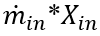
The mass flows ![]() and
and ![]() are determined from the elements attached to
the tank.
are determined from the elements attached to
the tank.
Momentum Conservation:
No momentum is passed from the flows entering the tank to the flows exiting the tank. The tank behaves like a plenum in terms of velocity.
Energy Conservation:
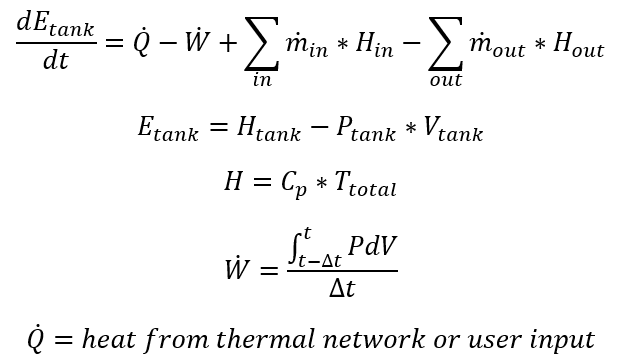
Note that the heat from thermal network or user input, can also be inferred from the user input for polytropic index, n. If n=1, the Q=W and the temperature is only a function of the heat capacity of the fluid in the tank and the energy of the fluid entering the tank. Other properties of the tank are solved as follows
- Tank Pressure: The tank pressure is the pressure of the gas in the tank,
which is the same as the pressure at the top of the liquid surface.
- Open tank: The tank pressure is set to a constant value, usually atmospheric pressure.
- Tank with a bladder: The expansion or contraction of the trapped gas in the enclosed tank determines the pressure. The polytropic process equation is used: P*V^n=constant. The user can input the polytropic index, n.
- Tank with a vent: The gas mass flow through the vent determines the pressure. If the gas mass flow through the tank goes to 0 then the polytropic process equation will be used.
- Port Pressure: The pressure at each port submerged in the liquid includes
the gravitational effect on pressure.
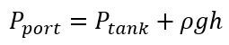
Where;
ρ=liquid density
g=gravity acceleration
h=height from port to top of liquid
- Fluid Volume:
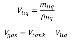
The
 is determined from the mass
conservation equation.
is determined from the mass
conservation equation. - Fluid species: The fluid species mass fraction in the tank
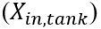 are determined by the species in the
tank and the species entering the tank.
are determined by the species in the
tank and the species entering the tank.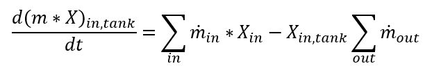
If an element entering a tank contains both a liquid and a gas the tank can separate the 2 species using the gas separation factor. The factor can be between 0 (no separation) and 1 (100% separation). This factor is used to modify the summation of
 term in the equation above.
Tank Component Outputs
The following listing provides details about Tank Component output variables.
| Name | Description | Units |
|---|---|---|
| TANK_COMPONENT | Component ID | Unitless |
| ASSOCIATED WITH CHAMBER |
Chamber ID which Tank component is associated with
|
Unitless |
| TANK_VOLUME | Volume of the Tank Component | gal |
| PORT | Port ID to which element is connected | Unitless |
| ELEMENT | Element ID that is attached to the Tank | Unitless |
| STAT_PRES | Static Pressure | psi, mPa |
| DIRECTION |
Flow Direction;
|
Flag |
| MASS_FLOW | Mass flow rate | PPS or kg/s |
| VOL_FLOW | Volumetric flow rate | |
| HEIGHT_TO_SURFACE | Surface height | in, m |
| FLUID_PHASE |
Fluid phase information
|
Flag |
| FLUID_TYPE | Material type of the fluid | Unitless |
| STEP | Mission step | Unitless |
| MISSION_TIME | Mission time | Sec |
| SURFACE_PS | Surface static pressure at each time step | psi, mPa |
| FLD_VOLUME | Volume of the filled volume at each time step | gal, m3 |
| SURFACE_HGHT | Liquid surface height at each time step | in, m |
| FLD_MASS | Filled mass at each time step | lbm, kg |
| FILL_RATE | Filling rate | gpm, kg/m3 |
| EMPTY_RATE | Emptying rate | gpm, kg/m3 |
| ODE_METHOD | ODE method information | Flag |
| STATUS |
Tank status
|
Flag |