Accumulator Components
Accumulator Component General Description
Anaccumulator is a pressure storage reservoir in which the fluid is held under pressure that is applied by an external source. The external source can be an engine, a spring, a raised weight, or a compressed gas. An accumulator enables a hydraulic system to cope with extremes of demand using a less powerful pump, to respond more quickly to a temporary demand, and to smooth out pulsations.
Quick Guide for Creation in the GUI
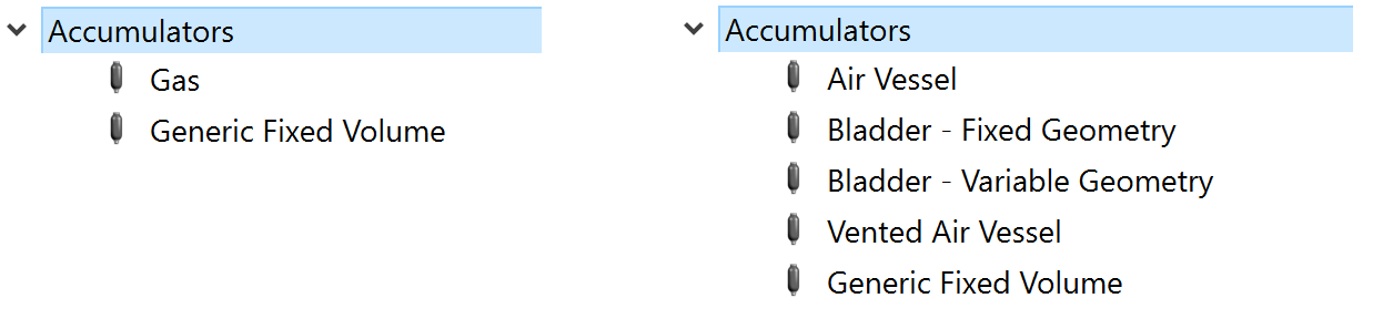
There are two accumulator subtypes under “Compressible Gas Elements” section and five accumulator subtypes under “Incompressible Liquid Elements” section available in Flow Simulator.
Accumulator Component Inputs
Table of the inputs for the Accumulator component.
| Element Specific Accumulator Component Input Variables | ||
| Index | UI Name (. flo label) | Description |
| 1 | Type (CPTYPE) | Type of component. See common component inputs table above for a full list. |
| 2 | Subtype (SUBTYPE) |
“Air Vessel” contains a liquid and a trapped gas. Elements carry the liquid in and out of the accumulator. The trapped gas is not in a bladder. “Bladder - Fixed Geometry” contains a liquid and a trapped gas in a bladder. Elements carry the liquid in and out of the accumulator. Only volume is needed to describe accumulator geometry “Bladder - Variable Geometry” contains a liquid and a trapped gas in a bladder. Elements carry the liquid in and out of the accumulator. Accumulator geometry can be described in detail using height and cross section area. “Gas” contains a gas and no liquid. Elements carry the gas in and out of the accumulator. “Vented Air Vessel” contains a liquid and a gas. Elements carry the liquid in and out of the accumulator. The gas can vent. The gas vent geometry and losses are described in the accumulator input. “Generic Fixed Volume” contains a liquid or a gas but not both (unless a 2-phase homogenous mixture is being used). Multiple elements carry the fluid in and out. |
| 3 | ASSOC_CHAM | Chamber that is used to represent the fluid in the accumulator in the solver. |
| 4 | Geometry Type (GEOM_TYPE) |
Type of geometry inputs. Fixed Geometry: Constant cross section area or just volume Variable Geometry: Height vs Cross section area Variable Geometry: Height vs Volume |
| 6 | Accumulator Volume (TOTAL_VOLUME) | The accumulator volume |
| 8 | Accumulator Cross-Section Area (CS_AREA) | The accumulator cross section area |
| 9 | Accumulator Height (TOTAL_HEIGHT) | Height of the accumulator |
| 10 | Base Level Elevation (BASE_LVL) | Elevation at the bottom (base) of the accumulator. Used for pressure change due to gravity. |
| 6 | Liquid Type or Gas Type (FLUID_SPECIES) | Identifies the type of fluid in the accumulator |
| 7 | Inlet Diameter (ARM1_DIAM) | Opening diameter for the element attached to the accumulator |
| 8 | Gas Valve Inflow Diameter (VENT_IN_DIAM) | Diameter of vent opening for air entering the accumulator. Only needed for subtype 5. |
| 10 | Gas Valve Outflow Diameter (VENT_EX_DIAM) | Diameter of vent opening for air exiting the accumulator. Only needed for subtype 5. |
| 11 | Inflow Loss Coefficient (ARM1_INLET_K) |
Pressure loss coefficient for fluid entering the accumulator.
|
| 12 | Outflow Loss Coefficient (ARM1_EXIT_K) |
Pressure loss coefficient for fluid exiting the accumulator.
|
| 13 | Initial Mass Flow Rate or Volumetric Flow Rate (FLOW_RATE) |
A volumetric flow rate or mass flow rate used for the initial flow rate entering or leaving the accumulator. Behaviour depends on the accumulator subtype. |
| 14 | Polytropic Index (Inflow)(POLYTROPIC_IN) | Polytropic Index for contracting gas (liquid flowing into the accumulator). |
| 15 | Polytropic Index (Outflow)(POLYTROPIC_EX) | Polytropic Index for expanding gas (liquid flowing out of the accumulator). |
| 16 | Gas Pressure (GAS_PRESSURE) | Initial gas pressure in the accumulator. |
| 17 | Gas Volume (GAS_VOLUME) | Initial gas volume in the accumulator. |
| 18 | External Gas Pressure (EXT_PRESSURE) | Ambient pressure for the vented gas in the Vented Air Vessel |
| 19 | Liquid Level (LIQ_LVL_OPT_1) | Initial height of the liquid in the accumulator |
| 20 | Liquid Level When Air Valve Closed | Liquid height at which the valve in the Vented Air Vessel will close. Liquid height below this level the valve is |
| 21 | Maximum Pressure (MAX_PRESSURE) | This is not used in the solver. |
| 22 | Precharge Pressure (PRE_CHRG_PRESS) |
Pressure of gas in the bladder before any liquid is put in the accumulator. Its used to set the initial gas pressure if an initial gas volume is provided. |
| 23 | Gas Constant (GAS_CONSTANT) | Gas property for the vented gas in the Vented Air Vessel |
| 24 | Specific Heat Ratio (SPECHEAT_RATIO) | as property for the vented gas in the Vented Air Vessel. Also know as gamma. |
| 25 | Thermodynamic Process Type |
Gas expansion or contraction treatment. Polytropic process (enter index); Pres*Vol^index = constant Isentropic process (use fluid gamma); Pres*Vol^gamma = constant |
| 26 | HEIGHT |
Table of heights for the accumulator for the variable geometry option. Height values should be in ascending order and start at 0.0 and end at the maximum height of the accumulator. |
| 27 | CS_AREA | Table of cross section areas of the accumulator for the variable geometry option. |
| 28 | VOLUME |
Table of volumes of the accumulator for the variable geometry option. Volume at height=0 should be 0. Other volumes should be total volume of the accumulator below the height. |
Accumulator Component Theory Manual
This section contains a governing equation of how mass, momentum & Energy conservation for all accumulator subtypes. Implicit Time Stepping solution is used to solve conservation equation as explained below.
| Nomenclature: | |
| V: volume | |
| A: cross section area | gc: Gravitational Constant |
| P: pressure | R: gas constant |
| T: Temperature | |
| V: volume | t: time |
| Cp: Specific Heat | |
| Subscripts: | |
| t: total | liq: liquid |
| s: static | g: gas |
| Superscripts: | |
| n: iteration |
Generic Fixed Volume and Gas Chamber
Mass Conservation
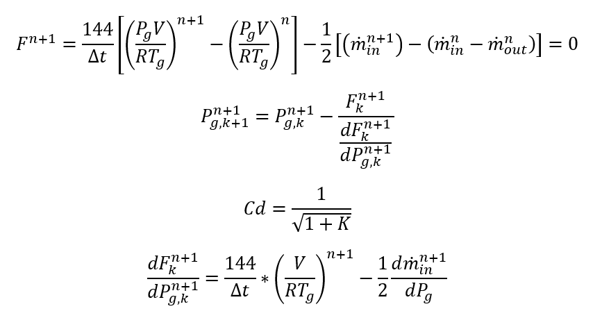
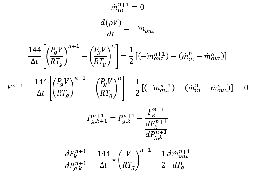
Compressible Flow
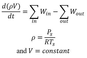
Mass accumulated inside the control volume is
Assuming first order backward time-stepping
Then, we define the residual equation similar to steady solver except for transient terms
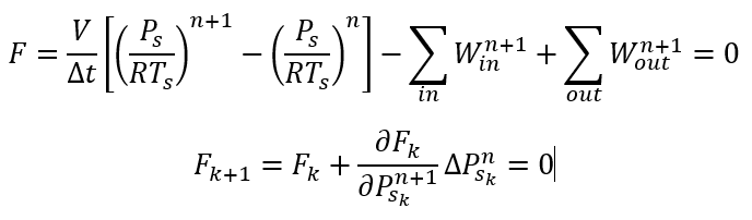
We need to calculate:
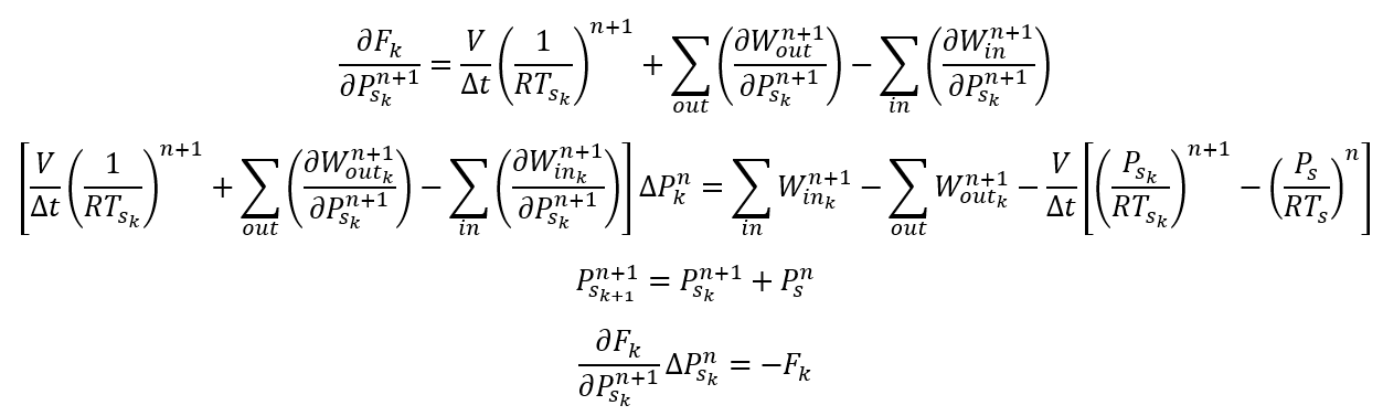
For 2nd order central time stepping
Incompressible Flow
Mass accumulated inside the control volume is
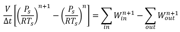
Assuming first order backward time stepping
![]()
Then, we define the residual equation similar to steady solver except for transient terms
Since density is a strong function of temperature and weak function of pressure, we assume temperature is independent of pressure
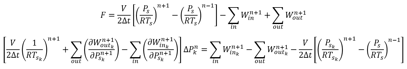
For 2nd order central time stepping
Momentum conservation
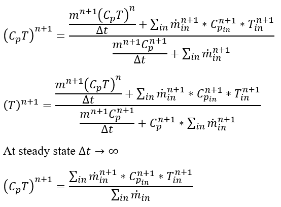
Energy conservation
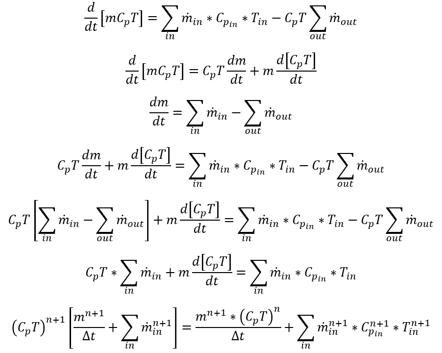
Air Vessel, Vented Air Vessel, Bladder Fixed Geometry and Bladder Variable Geometry
The following derivations hold for all the following sub-types: Air Vessel, Vented Air Vessel, Bladder Fixed Geometry and Bladder Variable Geometry.
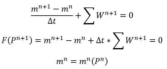
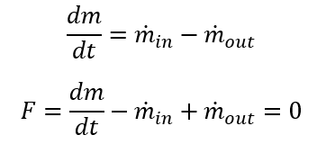
Mass Conservation
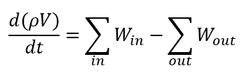
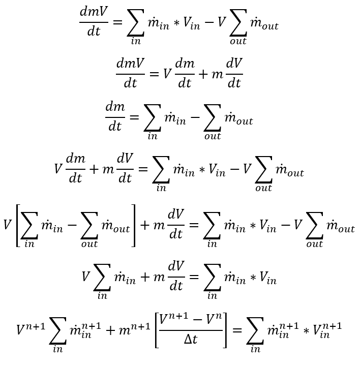
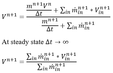
The continuity equation with the classical mass flux convention is given as
![]()
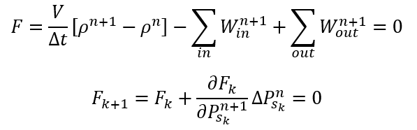
Using a first order backward Euler time stepping, we get
Then the Jacobian matrix becomes:
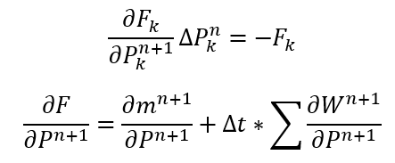
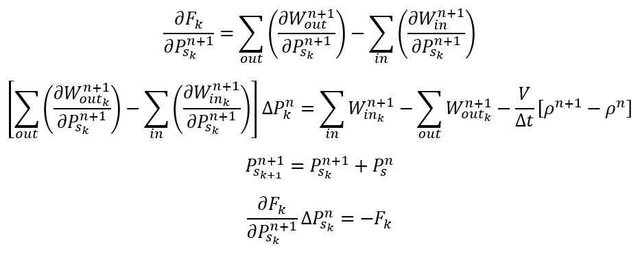
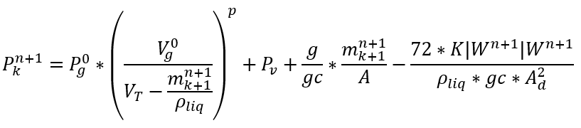
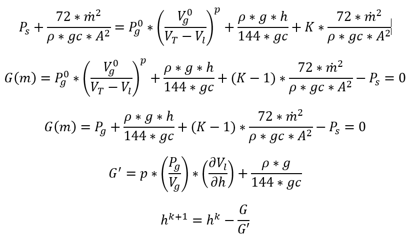
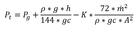
Pressure at the exit of the accumulator will be given as
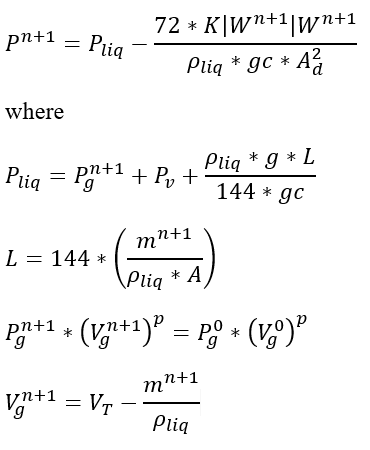
For each time step and inner iteration, we should calculate mass. Since we have a single equation for 2 unknowns, we will assume the previous iteration’s flow rate while calculating the remaining mass
Then, we have to solve for a non-linear equation for ![]()
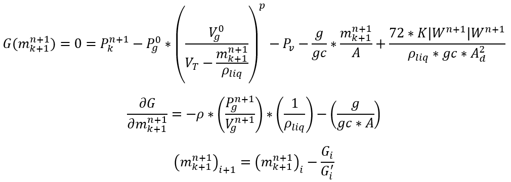
G is the residual equation which needs to converge to a very small number.
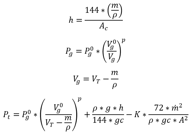
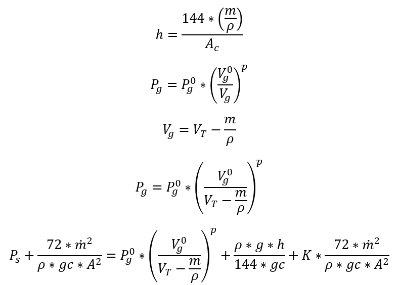
Finding the mass inside the volume:
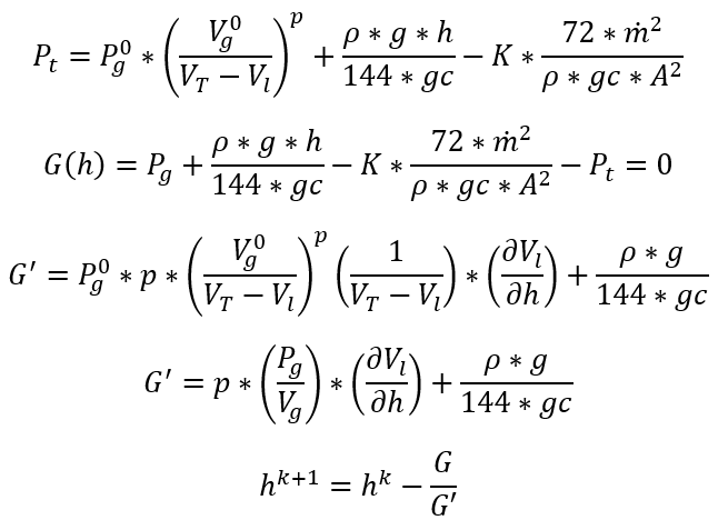
Now that we have defined the main residual equation, we will look at the calculation of remaining mass inside the volume. Since it will be mainly a function of h, or fluid height, the resulting equation will be in terms of h:
Case 1: Emptying
Case 2: Filling
Correcting the Continuity Equation
First order implicit Finite Difference:
![]()
Case 1: Emptying:
![]()
Only contribution to Jacobian matrix will be on the off-diagonal term
![]()
Case 2: Filling:
![]()
Only contribution to Jacobian matrix will be on the off-diagonal term
![]()
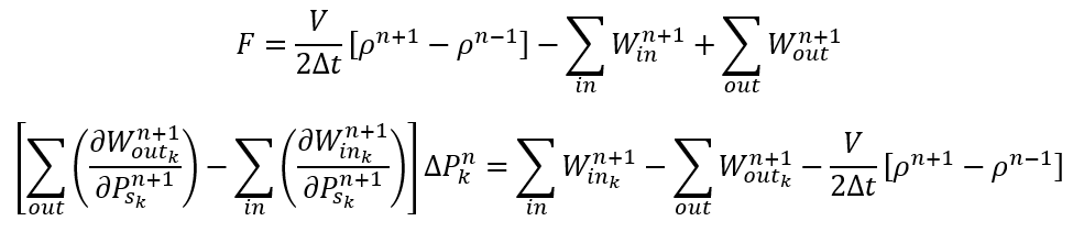
Second order implicit Finite Difference:
![]()
Case 1: Emptying:
![]()
Only contribution to Jacobian matrix will be on the off-diagonal term
![]()
Case 2: Filling:
![]()
Only contribution to Jacobian matrix will be on the off-diagonal term
![]()
Momentum and Energy Conservation
Case 1: Emptying Volume
In the above equation + if filling, and – if emptying
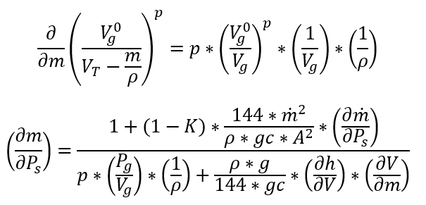
Taking ![]() derivative
derivative
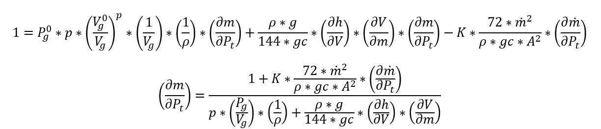
Case 2: Filling Volume
![]()
In the above equation + if filling, and – if emptying
Taking ![]() derivative
derivative
Special Case: Ventilation Option for the Vented Air Vessel
If the ventilation is on, we need to calculate the mass of the trapped gas
![]()
If ![]() , we will have in flow
, we will have in flow
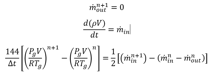
If ![]() , we will have out flow
, we will have out flow
Accumulator Component Outputs
The following listing provides details about Accumulator Component output variables.
| Name | Description | Units |
|---|---|---|
| ACCUMULATOR_COMPONENT | Component ID | Unitless |
| ASSOCIATED WITH CHAMBER |
Chamber ID which Tank component is associated with
|
Unitless |
| SUBTYPE | Subtype of the accumulator component | Unitless |
| FLUID_TYPE | Material type of the fluid | Unitless |
| GAS & GENERIC FIXED VOLUME ACCUMULATOR | ||
| GAS MASS | Mass of the gas | lbm, kg |
| GAS MASS ACCUMULATION RATE | Accumulation rate of the gas mass | lbm/s, kg/s |
| GAS MASS FLOW RATE | Gas mass flow rate | lbm/s, kg/s |
| GAS PRESSURE | Gas pressure | psi, MPa |
| VENTED AIR VESSEL ACCUMULATOR | ||
| LIQUID MASS | Mass of the liquid | |
| LIQUID MASS ACCUMULATION RATE | Accumulation rate of the liquid mass | lbm/s, kg/s |
| LIQUID MASS FLOW RATE | Liquid mass flow rate | lbm/s, kg/s |
| GAS PRESSURE | Gas pressure | psi, MPa |
| GAS VOLUME | Gas volume | ft3, m3 |
| LIQUID VOLUME | Liquid volume | ft3, m3 |
| LIQUID LEVEL | Liquid level in the accumulator | in, m |
| BASE LEVEL | Base level in the accumulator | in, m |
| BLADDER FIXED GEOMETRY & BLADDER VARIABLE GEOMETRY ACCUMULATOR | ||
| LIQUID MASS | Mass of the liquid | lbm, kg |
| LIQUID MASS ACCUMULATION RATE | Accumulation rate of the liquid mass | lbm/s, kg/s |
| LIQUID MASS FLOW RATE | Liquid mass flow rate | lbm/s, kg/s |
| GAS BLEDDER PRESSURE | Gas pressure | psi, MPa |
| GAS BLEDDER VOLUME | Volume of the gas in the accumulator | ft3, m3 |
| LIQUID VOLUME | Occupied volume of the liquid in the accumulator | ft3, m3 |
| LIQUID LEVEL | Occupied level of the liquid | in, m |
| BASE LEVEL | Base level | in, m |