Cylinder Components
Cylinder Component General Description
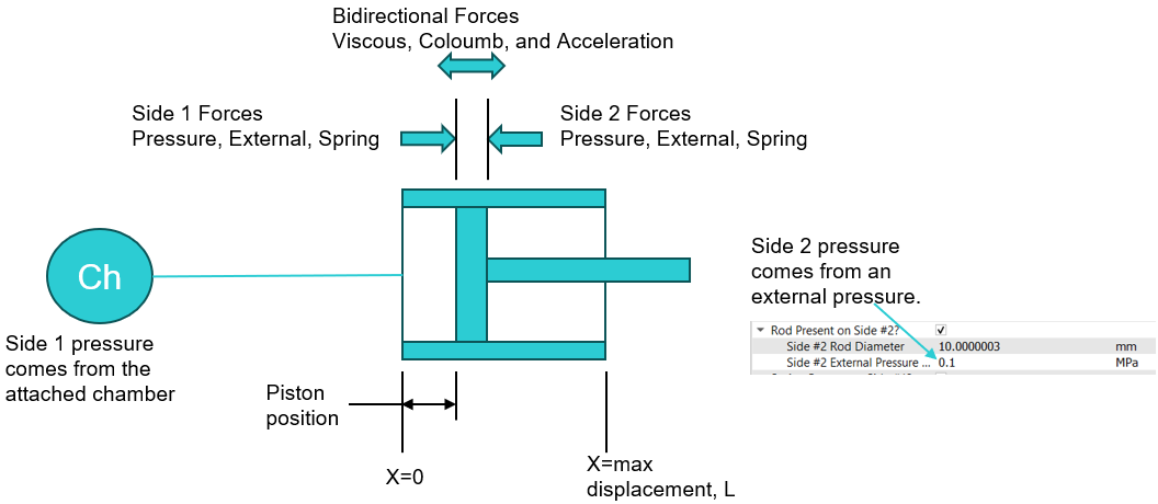
The pressure created by a fed working fluid is the basis for the operation of a hydraulic cylinder. Flow Simulator provides two types of piston cylinders. In a single-acting hydraulic cylinder, the working fluid comes into the cylinder from one hydraulic tank and presses down on the piston from one side, creating a return stroke of the rod. The return spring actuates a forward stroke.
In a double-acting cylinder, the return spring is absent, its role is performed by the second hydraulic tank, creating pressure on the piston from the other side and, as a result, providing reciprocating motions of the mechanism.
- Pressure forces
- Spring forces
- External force
- Viscous friction force
- Coloumb (Dynamic) friction forces
- Acceleration force
Quick Guide for Cylinder Component Creation in the GUI
There are two Cylinder subtypes under “Compressible Gas Elements” and “Incompressible Liquid Elements” sections in Flow Simulator.
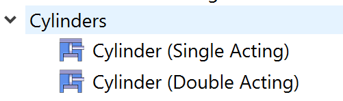
The Single Acting cylinder is attached to one chamber (side 1). The Double Acting cylinder is attached to two chambers.
Cylinder Component Inputs
Table of the inputs for the Cylinder Component.
| Cylinder Component Input Variables | ||
| Index | UI Name (. flo label) | Description |
| 1 | Type (CPTYPE) | Type of component. See common component inputs table above for a full list. |
| 2 | Subtype (SUBTYPE) |
Subtype of piston cylinder component;
|
| 3 | Cylinder Diameter (CYL_DIAM) | The diameter of the cylinder base face |
| 4 | Side 1 Rod Diameter (ROD_DIAM1) | Rod Diameter of 1st slide |
| 6 | Maximum Rod Displacement (MAX_ROD_TRAVEL) | The maximum displacement that the rod is allowed to travel by |
| 8 | Piston and Rod Mass (PISTON_ROD_MASS) | Total mass of the piston and rod |
| 9 | Leakage Coefficient (LEAK_COEF) |
The coefficient which describes the level of leakage between the sides of the cylinder base and the walls of the element. The leakage flow is proportional to the pressure difference across the piston. For more advanced leakage modeling, you can use a separate flow element that connects the one side of the cylinder and the other. Note 1: If there are different materials on either side of the pistons, the leakage coefficient should be 0, because for example, oil should not leak into gas. For mixtures, please use a Custom Material definition. Note 2: Only for Double Acting Cylinder piston |
| 10 | Reference Viscosity (MU_REF) | Viscosity value to calculate viscous force and viscous force is added in total drag force |
| 6 | Columb Friction Coefficient (COULOMB_FRIC) | Columb type of friction coefficient to be added in total drag force |
| 7 | (STICTION_FORCE) | Stiction force value to be added in total drag force |
| 8 | (STICTION_VEL) | |
| 10 | Spring #1 Force at Position=0 (F0_SPRING1) | The initial, preloaded force on the spring at position 0 |
| 11 | Spring #1 Constant (K_SPRING1) | Spring constant, k of 1st spring to be used in total spring force |
| 12 | Spring #2 Force at Position=0 (F0_SPRING2) | The initial, preloaded force on the spring at position 0 |
| 13 | Spring #2 Constant (K_SPRING2) | Spring constant, k of second spring to be used in total spring force |
| 14 | Initial Position (ROD_POSITION0) | The starting position of the cylinder base face |
| 15 | Slide #1 External Pressure on Rod (PS_EXTERNAL1) | The external pressure amount on the rod |
| 16 | (F_EXTERNAL1) | The initial, preloaded force on the spring at position L (Maximum Rod Displacement) |
| 17 | Slide #2 External Pressure on Rod (PS_EXTERNAL2) | External pressure on the rod |
| 18 | (F_EXTERNAL2) | The initial, preloaded force on the spring at position L (Maximum Rod Displacement) |
| 19 | Initial Velocity (ROD_VELOCITY0) | The initial velocity of the cylinder rod at the beginning of the transient run |
| 20 | Slide #1 Fluid Volume at Position =0 (VOL1_AT_POS0) | Fluid volume when the piston is at initial position |
| 21 | Slide #1 Fluid Volume at Position =0 (VOL2_AT_POS0) | Fluid volume when the piston is at initial position |
| 22 | Slide #2 Rod Diameter (ROD_DIAM2) | Slide second rod diameter |
| 23 | Spring #1 Constant (DISCRETIZATION) | Spring constant, k of first spring |
Cylinder Component Theory Manual
Single Acting Cylinder Schematic
Cylinder Initial Position
The spring forces and pressure forces on the piston must be balanced at the start of the transient. The initial position, x_o, input determines the spring forces and must be set correctly. The solver does not calculate or set this input so you must set it. Ignoring the effects of the wall friction or piston mass, the equation is:
Cylinder Governing Equations
Piston-Rod Force Variable Definitions
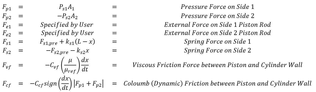
Force Balance Equation (Newton’s Second Law)
Where:
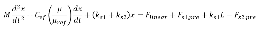
The Force Balance Equation can be re-written as a second order linear ODE.
There are two complications:
- The Coulomb (Dynamic) Friction term is either positive or negative depending on
direction of piston motion. This means the governing ODE of piston motion needs
to be split into two parts, one for left-to-right motion and the other for
right-to-left motion. In both cases, the initial position and velocity are the
initial conditions.
- The total pressure force and external force () is changing within each timestep.
Flow Simulator assumes linear variation within each
timestep, which is second order accurate, and helps when you want to take
relatively large fluid timesteps. However, it should be noted that you can
always achieve greater accuracy by taking smaller fluid timesteps.
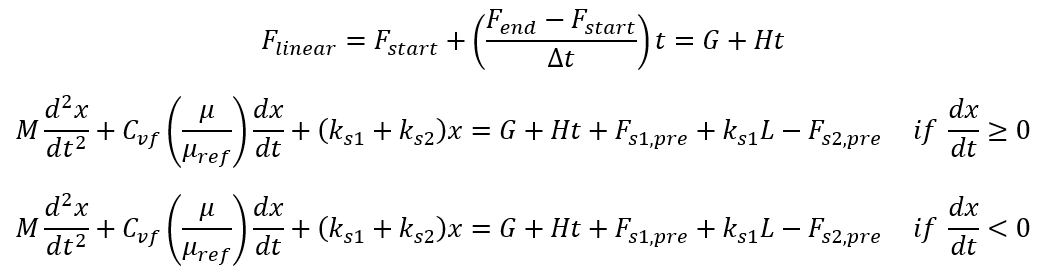
The governing ODE can be split into four distinct ODE regimes by introducing ![]() and parameters. (LR signifies left-to-right
motion and RL is right-to-left motion.)
and parameters. (LR signifies left-to-right
motion and RL is right-to-left motion.)
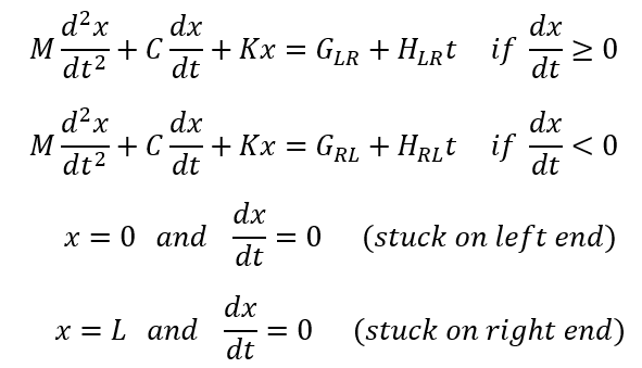
Depending on the ODE coefficients of the two non-trivial ODEs, the ODE solution can follow one of eight different equation forms.
![]()
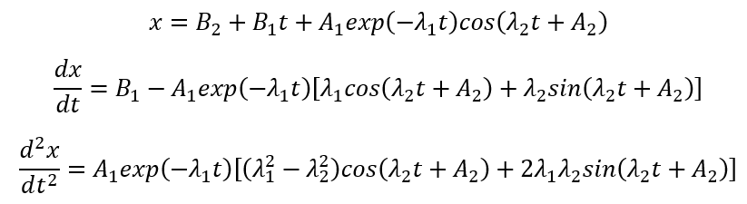
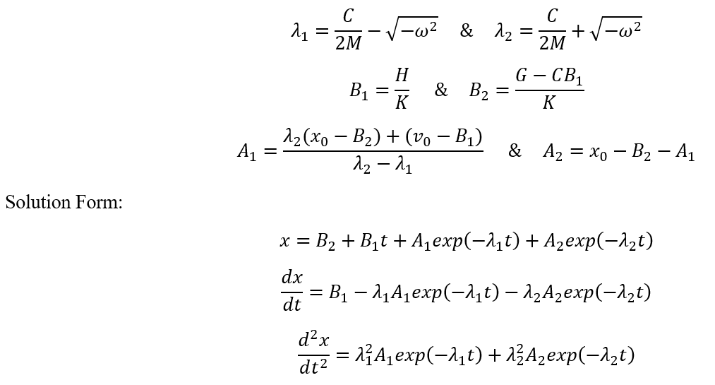
Under-damped when ![]()
Solution Parameters based on ODE Coefficients and Initial Conditions:
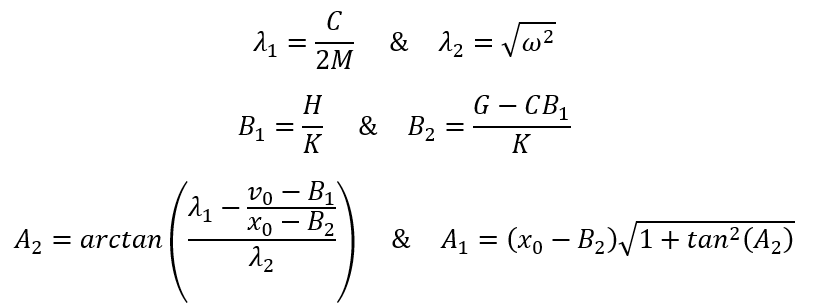
Solution Form:
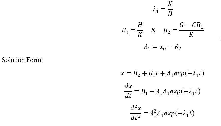
Over-damped when ![]()
Solution Parameters based on ODE Coefficients and Initial Conditions:
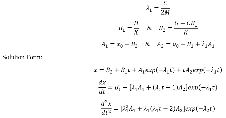
Critically Damped when ![]()
Solution Parameters based on ODE Coefficients and Initial Conditions:
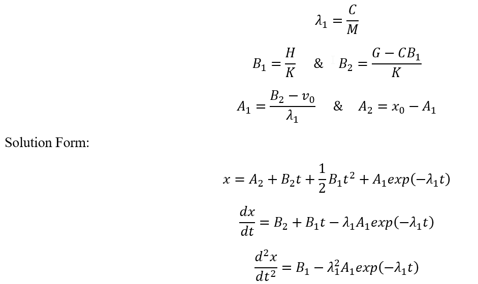
Spring-less when K=0
Solution Parameters based on ODE Coefficients and Initial Conditions:
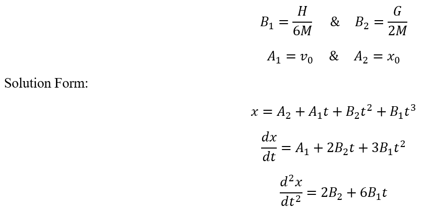
Spring-less & Friction-less when K=0 & C=0
Solution Parameters based on ODE Coefficients and Initial Conditions:
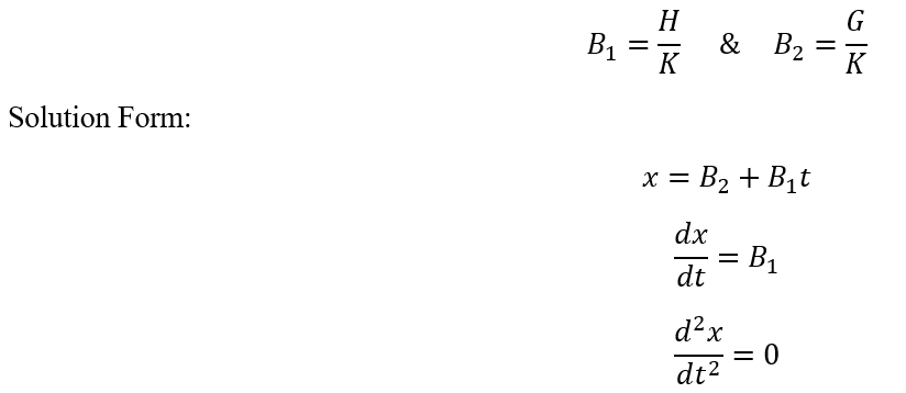
Mass-less when M=0
Solution Parameters based on ODE Coefficients and Initial Conditions:
Mass-less & Friction-less when M=0 & C=0
Solution Parameters based on ODE Coefficients and Initial Conditions:
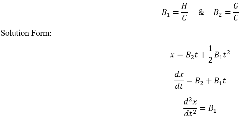
Mass-less & Spring-less when M=0 and K=0
Solution Parameters based on ODE Coefficients and Initial Conditions:
Adaptive Time-stepping
Detecting changes in four ODE regimes adaptively and adjusting the piston motion timestep and/or fluid timestep is critical to accurate results.
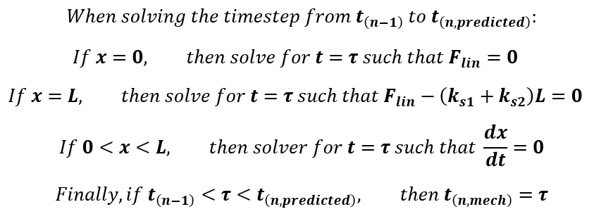
If the “Mechanical Only” adaptive option is chosen, then![]() is equal to
is equal to ![]() . The piston-cylinder solver will shorten the
piston motion ODE interval. A second (or sometimes more) piston motion solution
intervals will be required to reach
. The piston-cylinder solver will shorten the
piston motion ODE interval. A second (or sometimes more) piston motion solution
intervals will be required to reach ![]() . Therefore, there will be piecewise piston
motion solution in on the interval from
. Therefore, there will be piecewise piston
motion solution in on the interval from ![]() . However, the linearly varying force
assumption, which is usually due to time-varying pressures, still applies on the
interval from
. However, the linearly varying force
assumption, which is usually due to time-varying pressures, still applies on the
interval from ![]() . This means you a not resolving the fluid
pressure changes at the shorter timestep.
. This means you a not resolving the fluid
pressure changes at the shorter timestep.
If the “Coarse” adaptive option is chosen, then ![]() is set equal to
is set equal to ![]() , so the fluid timestep is shortened as well.
This achieves greater accuracy.
, so the fluid timestep is shortened as well.
This achieves greater accuracy.
The “Fine” adaptive option is like “Coarse”, expect with an addition constraint. If there is a spring, then there is a natural oscillation period based on the spring stiffness and piston-rod mass. The timestep will not be allowed to go higher than 1/N of the natural oscillation period. The default N is 12. You can change this input in the Advanced Options menu. This option should be used for Cylinder components with high coupling sensitivity to the fluid model – and where oscillations of the piston must be captured to correctly model the physical behavior of the system.
Finally, the “Off” option does not shorten either mechanical or fluid timestep. However, it does use a numerical trick to prevent spurious oscillations that occur when you require the piston to leave the end at the “wrong time”. It uses a smoothing option, described in detail in the following section, but only for the time-steps where the piston becomes unstuck.
Smooth Solution Option
The Cylinder Component provides an option to smooth the solution of oscillating pistons. Usually the fluid network will dampen the piston motion. Alternatively, you can specify viscous friction. However, in some cases, these two options may not be sufficient. If you do not know how much friction or fluid mass that is required for damping, but you know the piston motion should be smooth (non-oscillatory), then you can use the Smooth option. If the solution is in the underdamped mode, the smooth option will solve for piston motion including oscillations, and only at the last stage it zeros out the amplitude of the sine and cosine terms. For piston position, this is not usually important. However, for piston velocity, which directly affects cylinder port flow rates that are returned to the fluid solver, this can provide critical stabilization. This will aid both convergence robustness and solution accuracy. For all the other ODE regimes besides underdamped, the Smooth option does not take effect.
Mechanical & Fluid Coupling Method
To couple the piston motion with the fluid solver, the mass flow rate at the piston ports must be calculated. Here we define as the rate of mass entering the cylinder through the port.
![]()
The velocity ![]() term needs special treatment that is
analogous to unwinding in CFD. This helps to achieve a stable and accurate
solution.
term needs special treatment that is
analogous to unwinding in CFD. This helps to achieve a stable and accurate
solution.
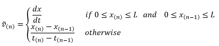
In other words, Flow Simulator uses the exact solution for velocity to calculate mass flow rate when the piston is not near the end positions. However, when the piston becomes stuck or unstuck from the end position, Flow Simulator uses a conservative differencing formula. This makes sure the rest of fluid circuit experiences the correct amount of mass release or mass removal by the cylinder.
Cylinder Component Outputs
The following listing provides details about Cylinder Component output variables.
Note: Currently, Cylinder Piston Component results are only in ENG unit.
| Name | Description | Units |
|---|---|---|
| MAIN SOLVER ITER CVG? | Information whether the main solver converged or not and if converged at which iteration | Flag |
| PISTON POSITION | Position of the piston at each time step | in |
| PISTON VELOCITY | Velocity of the piston | ft/s |
| PISTON ACCEL | Acceleration of the piston during the motion | ft/s2 |
| TOTAL LOAD FORCE | Total load force | Lbf |
| TOTAL PRESSURE FORCE | Total pressure force | Lbf |
| TOTAL SPRING FORCE | Total spring force (F_Spring + K_Spring*Distance) | Lbf |
| VISCOUS DRAG FORCE | Viscous drag force | Lbf |
| COULOMB DRAG FORCE | Coulomb drag force (coulomb_fric*pressure_force) | Lbf |
| STICTION DRAG FORCE | Stiction drag force | Lbf |
| CYLINDER END-WALL FORCE | Force on the cylinder end-wall | Lbf |
| NOT ROD FORCE | Rod force based on external pressure on rod | Lbf |
| INNER PS (SIDE 1 & SIDE 2) | Static Pressure inside | psi |
| ACCUM (SIDE 1 & SIDE 2) | Accumulated mass | Lbm |
| ACCUM RATE (SIDE 1 & SIDE 2) | Accumulation rate | pps |
| LEAKAGE UPTAKE (SIDE 1 & SIDE 2) | Leakage value | pps |
| EXTERNAL UPTAKE (SIDE 1 & SIDE 2) | External force | pps |
| DYNVISC (SIDE 1 & SIDE 2) | Dynamic viscosity of the fluid | Lbm/ft/hr |
| PRESSURE FORCE (SIDE 1 & SIDE 2) | Side 1’s pressure force | Lbf |
| SPRING FORCE (SIDE 1 & SIDE 2) | Side 1’s spring force | Lbf |