Plate Fin Heat Exchanger Component
Description
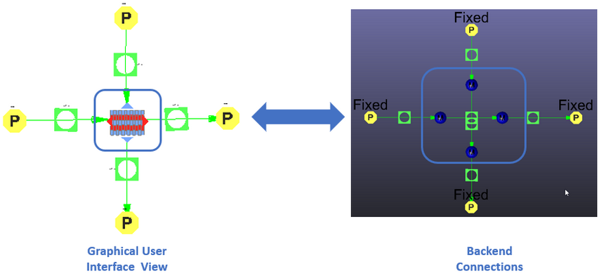
The Plate Fin Heat Exchanger can be used in Compressible and Incompressible (hydraulic and non-hydraulic) simulations. The component has four fluid connections and it models heat exchange between two streams in a network. Heat Exchangers in Flow Simulator come with four hidden chambers representing the four sides of the heat exchanger. The Plate Fin Heat Exchanger uses Orifice elements (Compressible or Incompressible) in the backend to model restriction losses (pressure loss) of both flow paths based on Friction Factor correlations for different Fin Configurations and characteristic flow area. The Heat addition/removal is calculated by the E-NTU method in the PlateFin Hx module, and Q (Heat Addition/Removal) is supplied to Orifice Elements to predict the temperatures of the exiting fluids.
Important modeling aspects when using the heat exchanger components include:
- The Hot Side circuit must be connected to line 1 (red part in the image below) and
the Cold Side circuit must be connected to line 2 (the blue part in the image
below):
Figure 3. 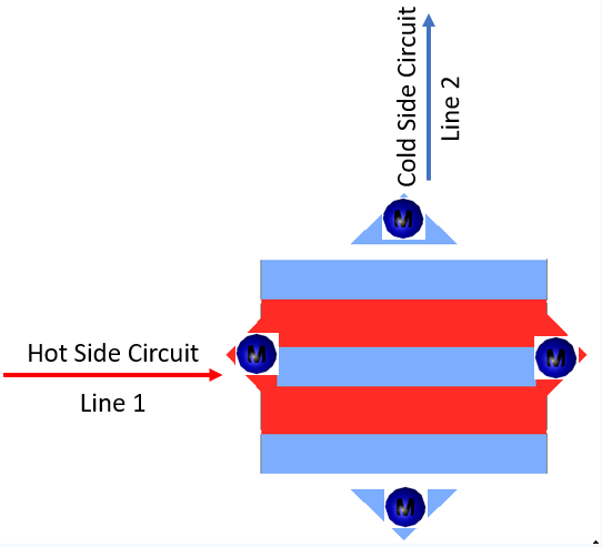
- The Hot/Cold Side circuit line must be connected with either compressible or Incompressible set of elements. Mixing of elements sets for a Hot/Cold side circuit line is not allowed. Plate Fin Heat Exchanges supports following fin configurations. The Heat Transfer Coefficient and Friction factor for various configurations are calculated based on public literature which are provided in theory manual below.
Plate Fin Heat Exchanger Element Inputs
| Index | Field | Description |
|---|---|---|
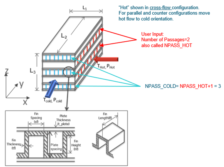
| 1 | Length in X Direction (L1) | Dimensions of Heat Exchanger (Refer Image Above) |
| 2 | Length in Y Direction (L2) | Dimensions of Heat Exchanger (Refer Image Above) |
| 3 | Length in Z Direction (L3) | Dimensions of Heat Exchanger (Refer Image Above) |
| 4 | Number of Passages (NPASS) | Number of Hot Passages |
| 5 | Flow Configurations | Configuration of Heat Exchanger
|
| 6 | Fin Configurations | Fin configurations
|
| 7 | Fin Material | Fin Material. By default, two Standard Materials are listed.
Any Custom Material defined using the Material Manager under the solid category is available for selection apart from the above-mentioned standard materials. |
| 8 | Fins per Inch | No of Fins per Inch |
| 9 | Plate Spacing (H) | Distance between Plates |
| 10 | Fin Thickness (t) | Thickness of Fin (Refer to Image Above) |
| 11 | Offset Length (w) | Offset Length (Used for Offset Fin Configurations) (Refer Image in Theory Sections) |
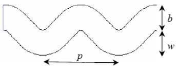
| 12 | Wave Length (p) | Wavelength (used for Wave Fin Configurations) (Refer to Image in Theory Sections) |
| 13 | Louver Pitch (Lp) | Louver Pitch (used for Louver Fin Configurations) (Refer to Image in Theory Sections) |
| 14 | Louver Height (Lh) | Louver Height (used for Louver Fin Configurations) (Refer to Image in Theory Sections) |
| 15 | Plate Material | Plate Material. By Default, two Standard Materials are listed.
Any Custom Material defined using the Material Manager under the solid category is available for selection apart from the above-mentioned standard materials. |
| 16 | Plate Thickness | Plate Thickness (Refer to Image Above) |
| 17 | Bar/end Plate Thickness | End Plate Thickness |
| 18 | Colburn J factor coefficient A J_ACOEFF | Coefficient A for Colburn J factor (Refer to Equations in Theory Manual) |
| 19 | Colburn J factor coefficient B J_BCOEFF | Coefficient B for Colburn J factor (Refer to Equations in Theory Manual) |
| 20 | Friction factor coefficient A F_ACOEFF | Coefficient A for Friction F factor (Refer to Equations in Theory Manual) |
| 21 | Friction factor coefficient B F_BCOEFF | Coefficient B for Friction F factor (Refer to Equations in Theory Manual) |
Plate Fin Heat Exchanger Theory Manual
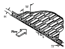
| Nomenclature | |
|---|---|
| H: Plate Spacing | P: Wave Length |
| Tf: Fin Thickness | Lp: Louver Pitch |
| W: Offset Length | Lh: Louver Height |
| Tp: Plate Thickness | Dh: Hydraulic Diameter |
| Fp: Fins per Inch | s: Offset Spacing |
| AO: Free Flow Area | : Mass flow rate |
| A: Surface Area | Density |
| Subscripts | |
| in, up, 1: Upstream station | C: Cold |
| ex, dn, 2: Downstream station | H: Hot |
Plate Fin Heat Exchanger uses e-NTU method to perform rating problem for a given heat exchanger. The step-by-step procedure is explained below.
Step: 1 -Surface geometrical properties
Determine geometric properties on each fluid side like:
- Number of passes on cold side and hot side.
If Length in Z Direction(L3) is provided, then No of Passages (NPASS) is calculated by
If No. of passage of hot side is provided, then Length in Z Direction (L3) is calculated from above equation.
- Free-flow area
For Parallel and Counter Flow
For Triangular fins Configurations
*
*
For Others:
*
*
For Cross Flow
For Triangular fins Configurations
*
*
For Others:
*
*
Hydraulic diameter Dh and Heat transfer surface area A:
Step: 2 – Mean Temperatures and Fluid Properties
Determine the Tout for hot and cold sides for the first iteration by assuming Heat Exchanger effectiveness ~0.75:
- Tmean for hot and cold sides.
- Dynamic viscosity for hot and cold sides @ Tmean.
- Prandtl number for hot and cold sides @ Tmean.
- Specific heat for hot and cold sides @ Tmean.
Step: 3 - Mass Velocities, Reynolds Numbers, and j and f Factors
- Core mass velocity (G) =
- Compute Reynolds number (Re) =
- Calculate Colburn factor (j) and Friction factors (f) for various fin configurations.
Plain Rectangular & Triangular channels:
Laminar Developing & Developed Flow Correlations:
Nusselt Number:
m = 2.27+1.65Pr^ (1/3)
y = 1/10 for Rectangular & 3/10 for Triangular
Friction Factor:
= z/ (L RE PR)
= z/ (L RE)
L = Characteristic Length Scale
Re and Nu are based on a characteristic dimension of the square root of the cross section area
Fully developed transitional & Turbulent flows:
Nusselt Number:
Friction Factor:
Where:
A = 0.0054, B = 2.3*10^-8, m = 2/3 for 2100<Re<4000
A = 0.00128, B = 0.1143, m = 3.2154 for 4000<Re<10^7
Offset Fins:
Cd = 0.88, drag coefficient due to blunt leading edges.
To account for Prandtl Number effects
Where:
Dh - hydraulic dia. (4.Ac/Pw)
dh - hydraulic dia. (4.Vf/At)
NuDh - Nusselt number for a rectangular channel for fully developed laminar flow
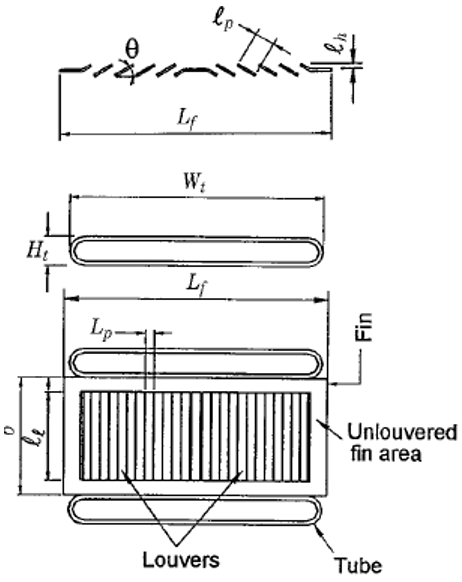
Louver Fins:
Lp - louver pitch
Ll - louver length
Fh - fin height (plate spacing)
Lh - louver height
Wavy Fins:
User Defined Option:
Where:
JA, JB, FA, FB are user-defined coefficients.
Step: 4 – HTC, Fin efficiency, Thermal conductance
- HTC calculation on hot and cold side:
- Fin efficiency:
- Overall surface efficiency:
- Thermal conductance:
+
Step: 5,6,7 NTU, Exchanger Effectiveness, and Outlet Temperatures
- Calculate heat capacity rates, Cmin, NTU.
- Calculate effectiveness (ε)
- Cross Flow
- Counter Flow
- Parallel Flow
- Cross Flow
- From the new ε, calculate Heat transfer rate (q) and Tout.
- Calculate the fluid properties again with the obtained Tout.
- Repeat the steps 2-7 until the Tout equals the previous iteration.
Step-8 -Pressure drop calculations
The total pressure drop across a plate fin Hx is given by
Core pressure drop calculations considering only Skin Friction losses.
| Name | Description | Units |
|---|---|---|
| Flow Configuration | Configuration of Heat Exchanger
(An echo of the user input). |
(None) |
| Plate Material | Plate Material (An echo of the user input). | (None) |
| Plate Thickness | Thickness of Plate (An echo of the user input). | in, m |
| X_Length | Length in X Direction (L1) (An echo of the user input). | in, m |
| Y_Length | Length in Y Direction (L2) (An echo of the user input). | in, m |
| Z_Length | Length in Z Direction (L3) (An echo of the user input). | in, m |
| Plate Area | Plate Area | In2, m2 |
| Effectiveness | Effectiveness of Heat Exchanger | (None) |
| NTU | Number of Transfer Units | (None) |
| Overall Conductance (UA) | Overall Conductance | BTU/hr.F, W/K |
| Q | Heat Added/Rejected | Btu/s, W |
| Wall Resistance | Wall Conductive Resistance | BTU/hr.F, W/K |
| NPASS | Number of Passes (An echo of the user input). | (None) |
| Fin Configuration | Fin configurations
(An echo of the user input). |
(None) |
| Fin Material | Fin Material (An echo of the user input). | (None) |
| MDOT | Mass Flow Rate | Lbm/s, kg/s |
| Plate Spacing | Plate Spacing (An echo of the user input). | in, m |
| Fin Thickness | Fin Thickness (An echo of the user input). | in, m |
| Fins_Per_In | Fins Per Inch (An echo of the user input). | in, m |
| Offset Len | Offset Length (An echo of the user input). | in, m |
| Wave_len | Wave Length (An echo of the user input). | in, m |
| Louver_pitch | Louver Pitch (An echo of the user input). | in, m |
| Louver height | Lover Height (An echo of the user input). | in, m |
| JAcoeff | Colburn J factor coefficient A (An echo of the user input). | (None) |
| JBcoeff | Colburn J factor coefficient B (An echo of the user input). | (None) |
| FAcoeff | Friction factor coefficient A (An echo of the user input). | (None) |
| FBcoeff | Friction factor coefficient B (An echo of the user input). | (None) |
| Ht_Surf_Area | Heat Transfer Surface Area | In2, m2 |
| HTC | Heat Transfer Coefficient | BTU/hr.Ft2.F, W/m2.K |
| Fanning Friction | Fanning Friction Factor | (None) |
| Loss_Coeff | Loss Coefficient (K) | (None) |
| PS | Static pressure | psia, MPa |
| PT | Total pressure | psia, MPa |
| TT | Total temperature of fluid | deg F, deg K |
| RE | Reynold Number | (None) |
| Rho | Density | lbm/ft^3, Kg/m^3 |
| CP | Specific Heat | Btu/(Lbm R), kJ/Kg.K |
| K | Thermal Conductivity | Btu/(hr ft R), W/m.K |
| DVISC | Dynamic Viscosity | Lbm/(hr ft), N s/m^2 |
| Area | Flow Area | In2, m2 |
References
- Shah, R. K., & Sekulic, D. P., “Heat Exchangers,” in Handbook of Heat Transfer, Chap. 17.
- Muzychka, Y. S., and Yovanovich, M. M., 2004, ‘‘Laminar Forced Convection Heat Transfer in Combined Entry region of Non-Circular Ducts,’’ Journal of Heat Transfer, Transactions of ASME, Vol. 126, pp. 54–61.
- M. S. Bhatti and R. K. Shah, "Turbulent and Transition Convective Heat Transfer in Ducts," in Handbook of Single-Phase Convective Heat Transfer, Chapter 4, John Wiley, New York, 1987.
- Muzychka, Y.S., and Kenway, G. 2009., “A Model for Thermal-Hydraulic Characteristics of Offset Strip Fin Arrays for Large Prandtl Number Liquids,” Journal of Enhanced Heat Transfer, 16, 73-92.
- C. J. Davenport, Correlation for heat transfer and flow friction characteristics of louvered fin, AIChE Syrup. Ser. 79, 19-27 (1983).