Defining a Unit Cell
Define a finite layered structure comprising layers of substrate and metal to solve with periodic boundary conditions. Alternately, imprint the structure onto a surface to construct frequency selective surfaces (FSS).
Some applications for the unit cell are as follows:
- Use as periodic structure for solving transmission and reflection coefficients.
- Auto-generate the geometry from a unit cell definition and attach the geometry to a flat or curved surface an use as a frequency selective surface (FSS).
-
On the Periodic Structures tab, in the
Structure group, select
 Unit Cell.
Figure 1. An example of defining a unit cell. 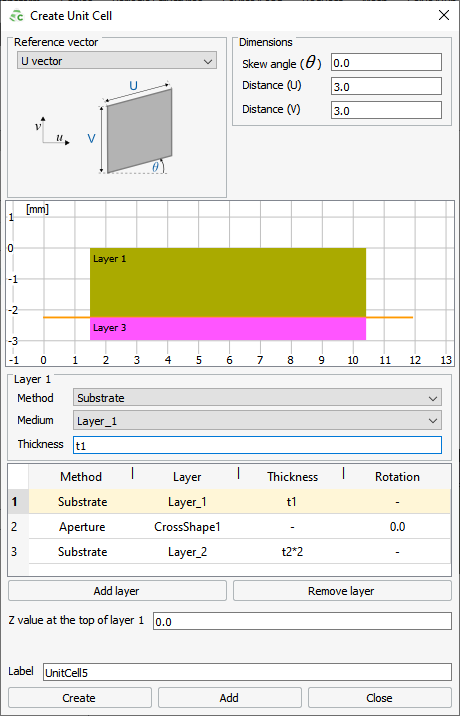
-
From the Reference Vector
drop-down list, select one of the following:
- To specify the skew angle relative to the U axis, select U vector.
- To specify the skew angle relative to the V axis, select V vector.
-
Under Dimensions, specify dimensions and orientation of
the unit cell:
-
For each layer, from the Method
drop-down list select one of the following:
- To specify a dielectric substrate or free space layer, select Substrate.
- To specify a metal layer, select Metal.
- To specify a metallic layer minus the shape, select Aperture.
Figure 2. An example of a single layer with a Cross shape. Left: Metal cross with no rotation or U and V ofsets; Centre: Metal cross with 45° rotation and U and V offsets of 1.5; Right: Aperture cross with 45° rotation and U and V offsets of 1.5. 
- In the Z-value at the top of layer 1 field, specify where the top of layer 1 is located.
- Click OK to define the unit cell and to close the dialog.
After a unit cell is defined, it available in the model tree (Construction tab) under .
Note: Next step is to auto-generate the geometry from the unit
cell definition.