On the Source/Load tab, in the
Ports group, click the Waveguide Port icon.
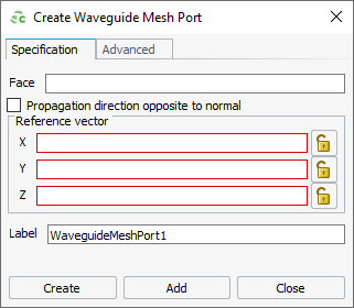
Figure 1. The Create Waveguide Mesh Port dialog.
Click the Specification tab.
In the Face field, use point entry to specify the face
using one of the following workflows:
In the 3D view, click on the relevant face.
In the details tree, click on the relevant
face.
A propagation direction and reference direction are automatically
defined.
If the propagation direction is not correct, you can change the
direction.
[Optional] Clear the Propagation direction opposite to
normal check box to change the propagation direction to be in
the same direction as the normal.
If the reference vector is not correct, you can specify the reference
vector.
[Optional] Under Reference vector, specify the reference
vector.
In the Label field, add a unique label for the waveguide
port.
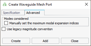
Click the Advanced tab.
Figure 2. The Create Waveguide Mesh Port dialog
(Advanced tab).
When the number of modes to be considered is not specified, Feko calculates the number automatically.
[Optional] To specify the number of modes, click the Manually set
the maximum modal expansion indices check box.
Select the Use legacy magnitude convention check box to
use the legacy definition of mode-dependent units (for example, for TE-mode it
is A/m; for TM-mode it is V/m).
Note: The default is to use the power-based definition of magnitude which is
common to all mode types.
Click Create to create the waveguide port and to
close the dialog.
 Waveguide Port icon.