Defining Domain Connectivity
Specify faces that are close together to be treated as connected
.
Note: Only supported for MoM and MoM/MLFMM
solutions.
-
On the Solve/Run tab, in the
Solution Settings group, click the
 Domain Connectivity icon.
Figure 1. The Create Domain Connectivity dialog. 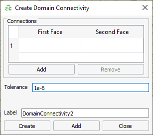
- Click the first row under First face to activate the field (indicated in blue) and click on the face either in the 3D view or in the details tree.
- Click the first row under Second face to activate the field and click on the face either in the 3D view or details tree.
-
Click Add if more
connections
are required. - In the Tolereance field, specify for each connection point, a tolerance distance to distinguish between regions, where a gap in the model is desired (or not desired).
- In the Label field, enter a name for the domain connectivity.
- Click Create to define the domain connectivity and to close the dialog.