Learn how to set up a simulation model and equipment, and define the generation of
bulk materials using EDEM Creator.
To set up the model:
Select the units of measurement to be used throughout EDEM. For more information about how to select units, see
Select
Units.
Click Tools > Options... and then select the Units tab.
In the Units tab, change the following measurement units:
Angle to degrees (deg)
Angular Acceleration to deg/s2
Angular Velocity to deg/s
Length to mm
Mass to kg
Mass Flow Rate to kg/s
Click OK.
Specify a title and description for the model.
Click Project in the Creator Tree.
In the Detailed View, specify a title (Conveyor Model).
Enter a description in the Description
field.
The model title and description is displayed in the Data Browser window. You
can close the Data Browser window to allocate more space for the windows that
will be used throughout this tutorial. If required, you can open the Data
Browser window again by right-clicking the menu bar and selecting
Data Browser.
Define the Bulk Material
The first step in setting up the model is to add a bulk material, particle shapes,
and their associated interaction properties.
To define the bulk material:
Add the bulk material.
Right-click Bulk Material in the Creator Tree,
select Add Bulk Material , and enter the name
'rock' in the Material highlighted field.
Alternatively, you can also use the icons in the Toolbar.
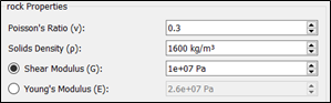
Define the bulk material properties.
Select rock in the Bulk Material section.
In the rock Properties dialog box, specify the
Poisson's Ratio, Solids
Density, and Shear Modulus.
Define the bulk material interactions.
In the Interactions section, click the icon.
In the Select Material dialog box, select
rock from the dropdown list to define the
interaction between all elements made of the material 'rock'.
Specify the coefficients as follows:
Create a new particle shape after defining the bulk material and interaction
properties.
Right-click rock in the Bulk Material section and
then select Add Particle > Add Multi-Sphere.
Enter the name 'rock Particle' in the Particle
highlighted field.
Optionally, you can rename the particle by
right-clicking the particle and selecting Rename
Particle.
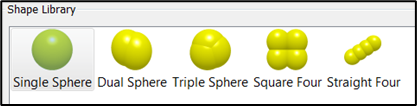
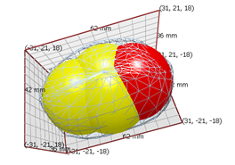
Define the spheres and properties.
Note: Multi-Sphere particles are made up of one or more
spheres. In this tutorial, we are going to import a CAD template of a rock
and fit four spheres to the template shape.
In the right-hand corner, in the Templates section, click
Edit....
In the Import dialog box, click
Import... and navigate to the folder that
contains the mesh file that will be used as the template.
In the Import Options dialog box, specify the
units of measurement to Millimeters (mm).
In the Mesh Control type ensure that all the
settings have the default values and then click
OK.
Note: In this
lesson, we are importing the particle template
rock_particle.stl. The STL file format is
already meshed, and changing the meshing options does not impact the
mesh of the imported template. For other file formats such as STEP
or IGES, you can modify the Geometry/template mesh by changing the
element size options in the Import dialog box.
Click the icon.
Rename the template to Rock Template, and then
click OK.
On the right-hand corner, in the Templates section, select
Rock Template from the Display
Templates dropdown list.
In the Creator Tree, select the rock particle and then select
Modify Shape in the Detailed View
section.
Select Single Sphere from the Shape Library as
follows:
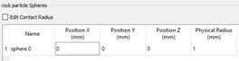
In the rock particle Spheres section, under the Viewer, change the
Physical Radius of the sphere from 0 to 18 mm and the Position X, Y, Z
to (0, -3, 0) mm.
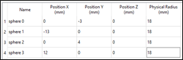
Add another sphere to the particle shape by right-clicking the rock
particle Spheres table and then selecting Add
Sphere.
Set the radius of this new sphere (sphere 1) to 18 mm and the Position
X, Y, Z to (-13, 0, 0) mm.
With one of the spheres selected from the table in the Rock Particles
Spheres section, click the Highlight Sphere icon in the View menu to distinguish the
spheres.
Add two more spheres and set their positions and radii as follows:
In the rock particle Properties section, select
Imported Template and then click
Calculate Properties.
Note:
When using the Imported Template option, the mass, volume,
and moments of inertia are calculated from the CAD
template.
Alternatively, you can use the Spheres option to calculate
these properties from a collective assembly of spheres.
An automated way to generate spheres to fill a template is
outlined in the following section. It is recommended in this
tutorial to use the manually created four-sphere
particle.
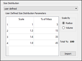
Specify the size distribution of the bulk material.
Expand the rock particle section in the Creator Tree and then select
Size Distribution.
In the Size Distribution section, select
user-defined from the dropdown list.
In the Scale By section, select Radius.
Right-click the User Defined Size Distribution
Parameters table and select Add
three times.
Specify the distribution parameters as follows:
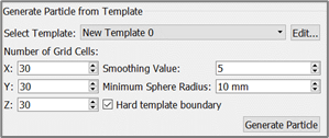
Generate Particles from a Template
When defining the Bulk Material, you specify the positions of the particles in
the template. You can use the alternative option of generating particles from a
template.
To generate particles from a template:
Select Bulk Material and then select Add
Bulk Material in the Creator.
Select the new Bulk Material and then right-click Add Shape from Library > Single Sphere.
Click Edit... next to the Select Template
dropdown list and import the CAD template (if not already
imported).
Use the following settings for the grid cells and sphere radius:
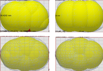
EDEM then automatically generates the
particle shape. These settings create approximately ten spheres that fill
the template with the higher fidelity model shown on the left and the
manually created four-sphere template on the right.
Define the Equipment Material
The next step in setting up the model is to add the equipment material that will be
used in the simulation.
To define the equipment material:
Add new equipment material.
Right-click Equipment Material in the Creator
Tree, and then select Add Equipment Material and
enter the name 'steel' in the highlighted field.
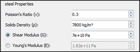
Define the equipment material properties.
Select steel in the Equipment Material
section.
In the steel Properties dialog box, specify the
Poisson's Ratio, Solids
Density, and Shear Modulus as
follows:
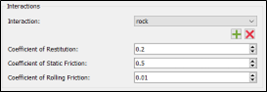
Define the bulk material - equipment material interaction.
In the Interaction dialog box, click the icon.
In the Select Material dialog box, select
rock from the dropdown list to define the
interaction between elements made of 'rock' and elements made of
'steel'.
Specify the coefficients as follows:
Define the Geometries
The next step in setting up the model is to define the conveyor and factory
Geometries used in the model.
To define the Geometries:
Import the conveyor Geometry that has already been created and is ready to be
imported into EDEM.
Right-click Geometries in the Creator Tree and
then select Import Geometry.
Navigate to the file conveyor_hopper.stl and import
it.
In the Geometry Import Parameters dialog box, set
Choose Units to
Millimeters.
Ensure that Merge Sections is not selected and that all the mesh
settings have the default values.
Click OK.
Select and right-click or press F2 to rename each
section appropriately as follows:
belt
hopper
lower hopper
guide_1
guide_2
Specify the conveyor kinematics.
Select belt in the Creator Tree Geometries
section.
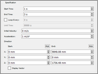
Right-click and then select Add Motion > Add Conveyor Translation (New Motion 1) and set up the Specification properties as
follows:
This creates an acceleration of 1 m/s2 between 1 and
3 s of simulation time.
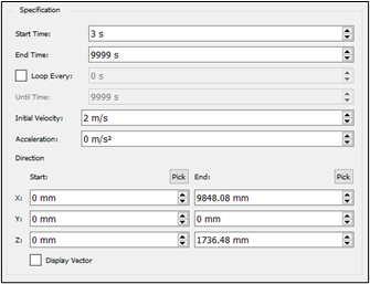
Right-click belt to add a second Conveyor
Translation (New Motion 2) and set up the second motion as follows:
Note: The second motion is set to have a constant
velocity of 2 m/s starting at 3 s. The motion of the belt is defined
by the Start and End points. In this case, the values have been
input manually. However, you can also use the Pick tool to pick a
Start and End point values. The Display Vector checkbox, if
selected, shows the direction of the selected motion in the
Viewer.
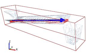
Create the particle factory plate.
Note: Particle factories are used to define where, when
and how particles will appear in a simulation. All factories must be based
on a section of Geometry (whether 'real' or 'virtual'). This defines the
area or volume in the model that produces the particles.
Right-click Geometries in the Creator Tree.
Select Add Geometry > Polygon and then enter the name 'factory_plate' into the
highlighted field.
Select the polygon and in the General section of the Detailed View set
the type to Virtual, since the plate is not a
physical part of the machinery.
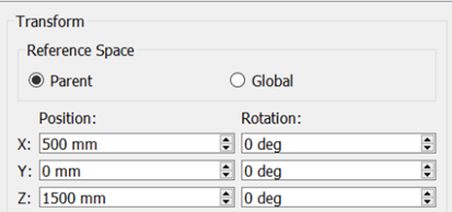
Expand factory_plate in the Creator Tree and
select the Transform subsection.
Set the position as follows:
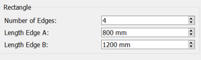
Select the Polygon subsection and specify the
Number of Edges and
Dimensions of the polygon as follows:
Create the particle factory.
Right-click factory_plate in the Creator Tree.
Click Add Factory.
Select the newly created factory and ensure that the Factory Type is set
to 'dynamic'. If not, right-click the new factory in the Creator Tree
and then select Change Factory Type.
In the Particle Generation section, select
Total Mass and set the value to 500 kg.
In the Generation Rate section, select
Target Mass and set the rate to 50
kg/sec.
Set the initial parameters for the factory.
In the Parameters section, ensure that you have
selected 'rock' from the Material dropdown list.
Set the Position to 'random' to ensure that the
particles are randomly created over the entire area of the plate.
Set the Velocity to 'fixed' and click the icon to set the velocity in the z-direction
to -2 m/s.
Select File > Save.
Define the Environment
The final step in setting up the conveyor model is to set the domain of the
simulation.
To define the environment:
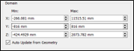
Select Environment in the Creator Tree.
Ensure that the Auto Update from Geometry checkbox is
selected.
Note: This automatically sets the domain of the simulation
depending on the Geometries present. Set the Domain Properties as
follows:
Set the gravity.
In the Gravity section of the Detailed View,
ensure that the gravity is set to -9.81m/s2 in the
z-direction.
 icon.
icon.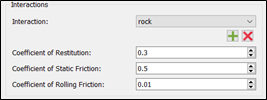
 icon.
icon.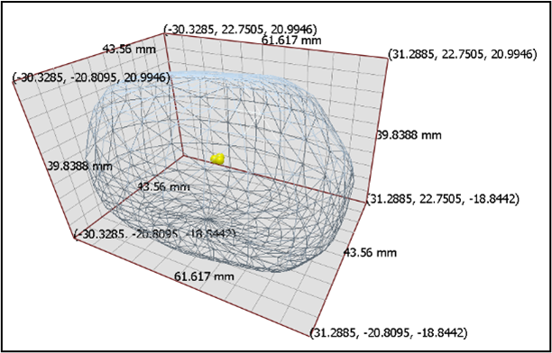
 icon in the View menu to distinguish the
spheres.
icon in the View menu to distinguish the
spheres.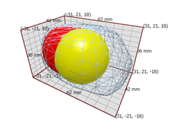
 icon to set the velocity in the z-direction
to -2 m/s.
icon to set the velocity in the z-direction
to -2 m/s.