SM_nPhase
Inputs
This section is dedicated to the specification of polyphase (n-phase) synchronous machines. This applies to synchronous machines with permanent magnets (SM-PM).
The user inputs, the cross section, the axial view and datasheet can be selected and displayed.
Here is the process to modify the structural data from the general data panel.
 |
|
|---|---|
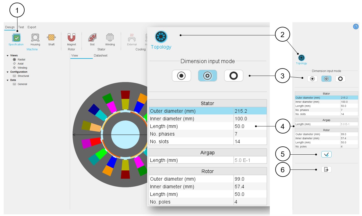
| 1 | Open the Specification panel (Click on the icon Specification). |
| 2 | Select the topology section for defining the structural data of the machine, meaning the main overall dimensions (stator and rotor outer and inner diameters) and characteristics like the number of slots, poles. |
| 3 | Choose a way to define the diameters of the machine and the airgap. See the dedicated section above. |
| 4 | Modify the values of structural data – when relevant, the
corresponding arrow is displayed on the view. See the list of input data below. |
| 5 | Button to apply inputs. |
| 6 | Icon to export data into a *.txt or *.xlsx file - please see above illustration. |
- Stator outer diameter
- Stator inner diameter
- Stator length
- Number of phases Note: The number of phases can be chosen over the range [3,15]. Only odd values are considered
- Number of slots
- Airgap length
- Rotor outer diameter
- Rotor inner diameter
- Rotor length
- Number of poles
The modification of the structural data can lead to the modification of the user input parameters in defining dimensions of parts like slots or magnets. When modifications occur, a warning is displayed.
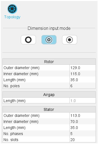
For machines with an outer rotor, the order of user inputs changes as shown below. The choice of the number of phases is not possible. The outer rotor machines are considered with a 3-Phase winding.
Advice for use
Please refer to the section “Topology / Structural data – Validity domain”.