Topology
Overview
The first step of the design consists of defining structural data of the machine meaning, the main overall dimensions (stator and rotor outer and inner diameters) and characteristics like the number of slots, poles, …
At any time, it is possible to access and modify the structural data from the Motor Factory design environment.
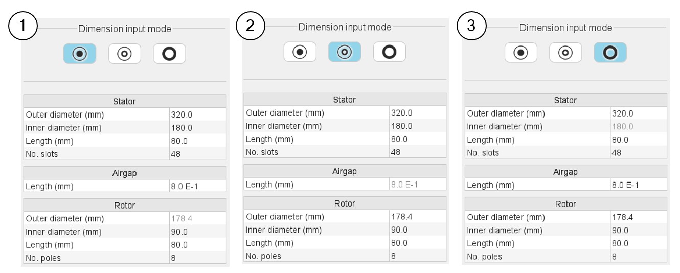
Method to define the airgap
Between the stator and the rotor, the airgap is a key region. Three ways are possible to define the length of the airgap.
 |
|
|---|---|
| 1 | User defines the inner diameter of the stator and the
airgap. The outer diameter of the rotor is automatically deduced (automatically computed value is displayed in grey color). |
| 2 | User defines the inner diameter of the stator and the outer
diameter of the rotor. The airgap is automatically deduced (automatically computed value is displayed in grey color). |
| 3 | User defines the outer diameter of the rotor and the
airgap. The inner diameter of the stator is automatically deduced (automatically computed value is displayed in grey color). |
Structural data – Validity domain
- Diameters: [1,20000] mm.
- Machine lengths: [1,20000] mm.
- Number of slots: [3, 2400].
- Number of poles: [2, 400].
- Number of phases: [3,15]. Available for polyphase winding. Only an odd number of phases are allowed.
- Number of bars: [5, 500]. Available to induction machines.
Working beyond these bounds is possible, but accuracy of the results is the responsibility of the user.
- Applied for all machines:
- Diameters: [1,1000] mm.
- Machine length: [1,1000] mm.
- Number of phases: [3,15]. Only an odd number of phases are allowed. Available for polyphase winding.
- Applied to all machines except induction machines:
- Number of slots: [3, 90].
- Number of poles: [2, 80].
- Applied to induction machines:
- Number of slots: [3, 144].
- Number of poles: [2, 20].
- Number of bars: [5, 180].
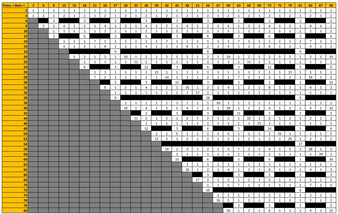
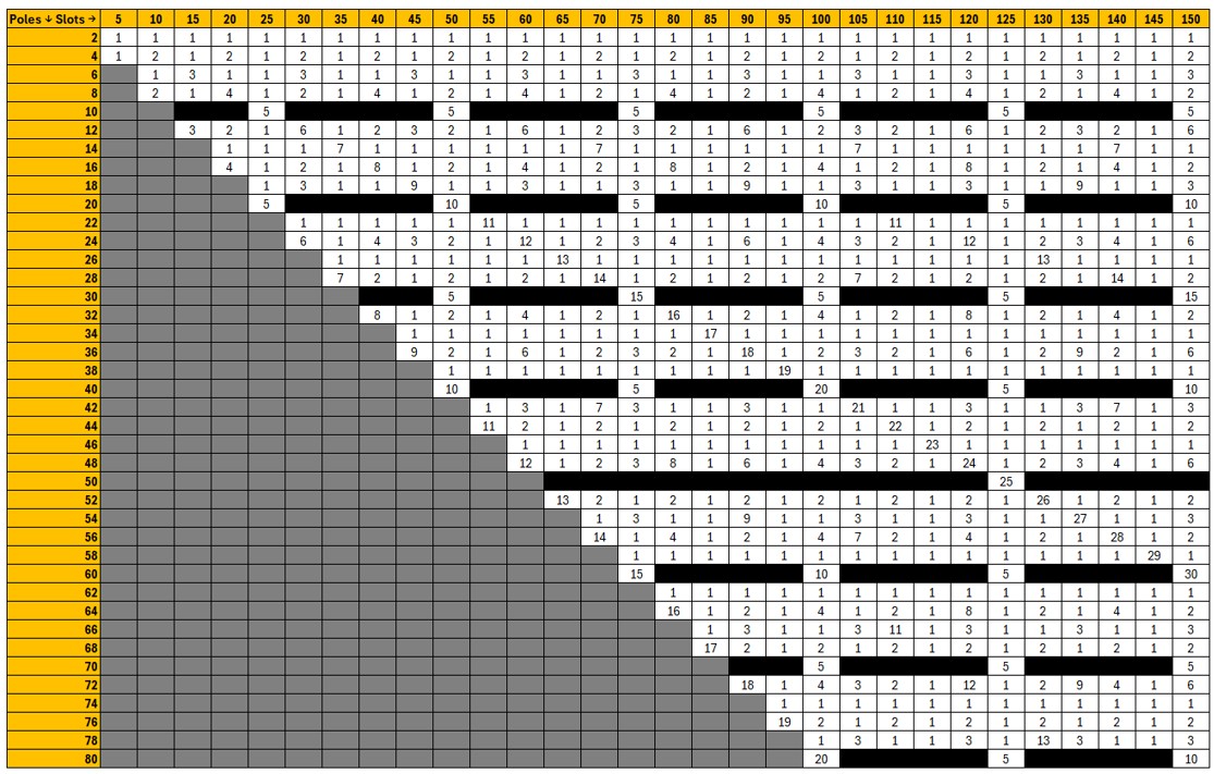
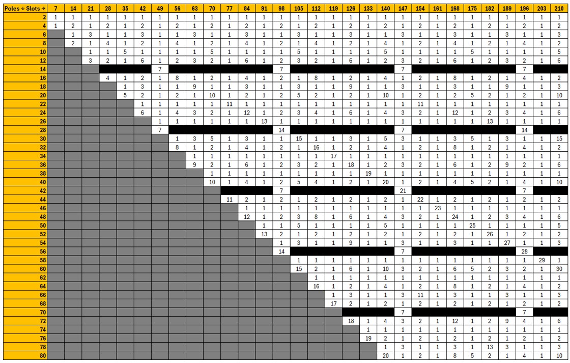
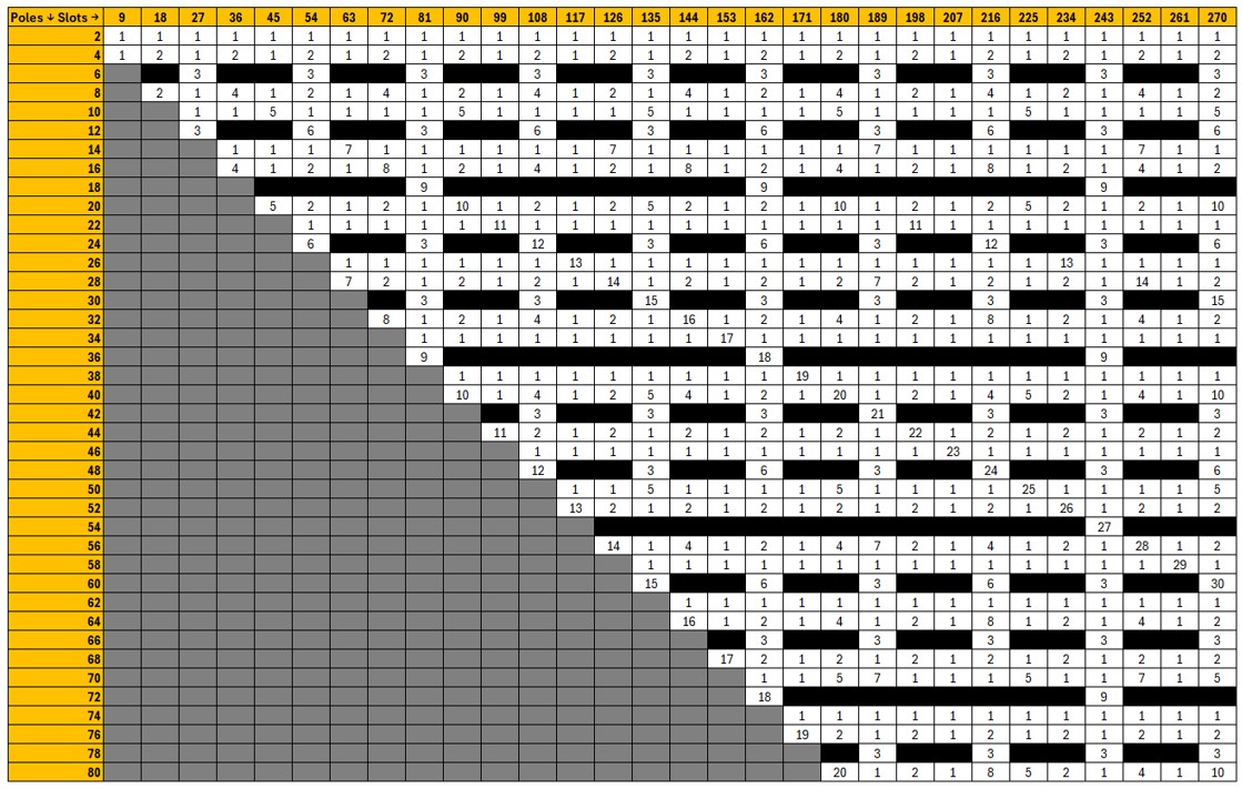
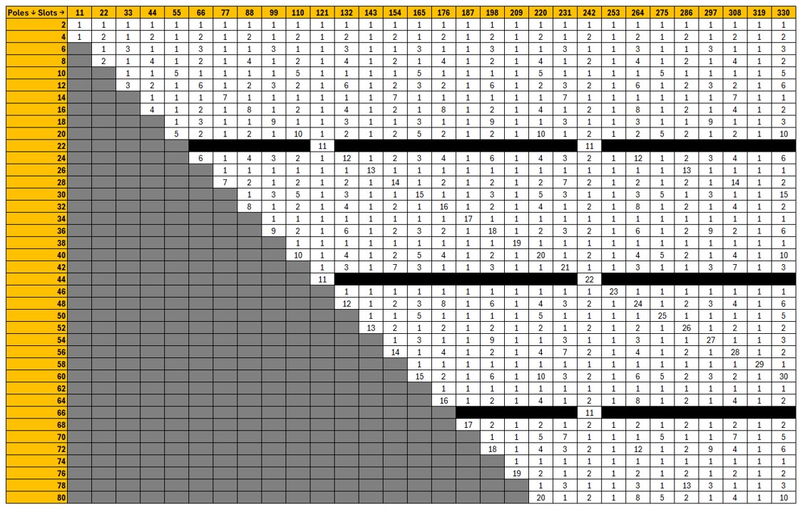
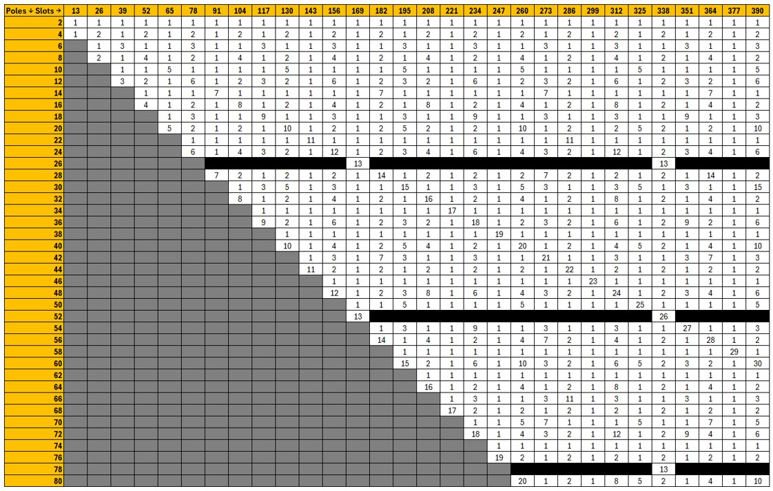
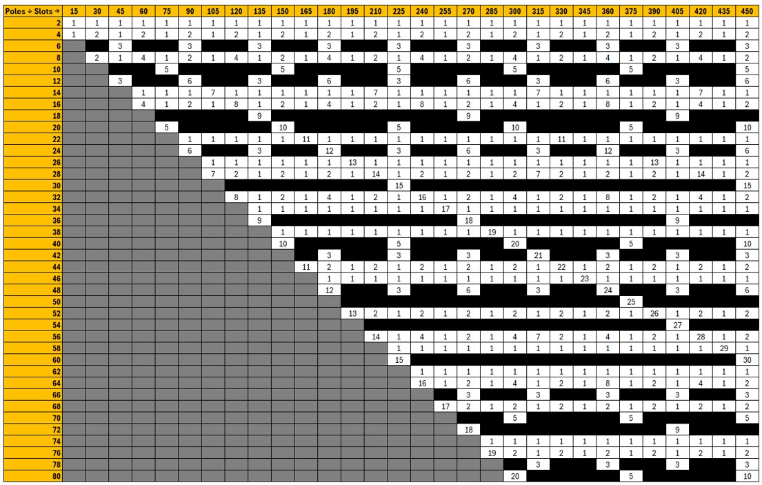
Combination of pole and slot number
Three tables representing a selection of combinations of number of poles and number of slots for the most typical number of phases (three, five and seven) are presented below.
- For the three-phase machines, the grey cells correspond to combinations with
a number of slots per pole per phase strictly lower than 0.25. These cases
are not allowed by our process.Note: If the hairpin winding type is selected only configurations with an integer number of slots per pole and per phase are allowed.
- The black cells correspond to forbidden combinations from a technological point of view.
- The numbers indicated in the other cells correspond to reduction coefficients to the resulting model in Altair Flux. For example, “1” means that the whole geometry is represented. “2” means that only half of the machine is represented, and “n” means that the 1/nth of the geometry is represented in the Altair Flux environment. That means, it gives a general idea of the size of the model in Altair Flux software. Higher value gives the reduction coefficient and faster computation for a given motor.