Design
Slot topology
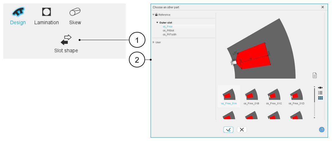
Choosing a new slot topology is possible by clicking on the "Slot shape" button. See the section “Choose part” for additional information. This opens a dialog box, allowing access to the slot libraries.
It allows visualizing, comparing, choosing, and importing another slot topology to modify in the current machine design.
 |
|
|---|---|
| 1 | Slot shape button allows accessing the slot libraries to change the slot topology. |
| 2 | Dialog box to visualize and to select the topologies of slots from the slot part libraries. |
Inputs / Outputs
 |
|
|---|---|
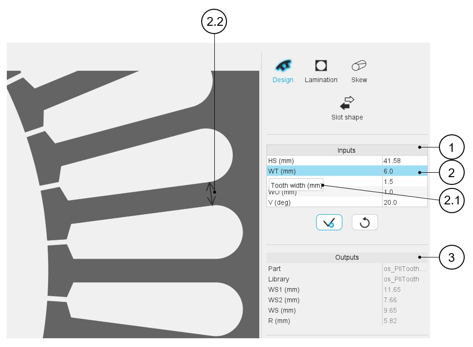
| 1 | User input parameter fields to enter the value. |
| 2 | Selecting a parameter highlights it. |
| 2.1 | Selecting a parameter displays the corresponding tooltip which completes information about the parameter. |
| 2.2 | Select a parameter label that displays the corresponding arrow on the picture. |
| 3 | Output parameters (read only data) to complete the description of
the topology. Note: The name of the part and
its original library are mentioned in this
section. |
Slot physical properties
- List of possible elementary regions for slots.Here is an example of regions for an outer slot.Note: The same principles apply to the inner slot.
Table 3. Regions for outer slot 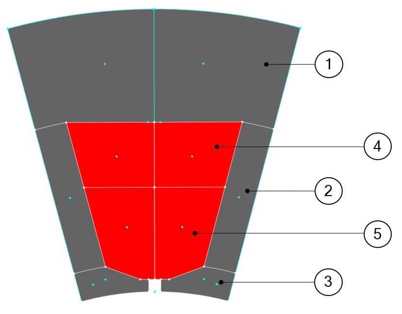
1 Yoke. 2 Tooth. 3 Tooth foot. 4 - 5 Coil conductors for describing superimposed coils or adjacent coil layout in slot. - Coil conductor, Tooth, Yoke and Tooth foot illustrated above.
- Insulating wedge or Ferromagnetic wedge
Figure 1. 1 - Insulating wedge or Ferromagnetic wedge location 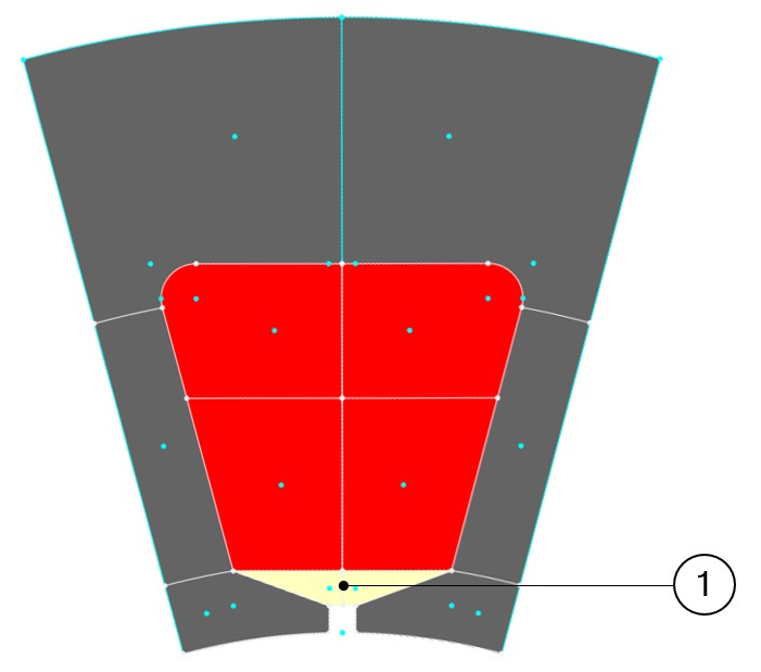
- Fluid “Intercoil” or Insulator “Intercoil” dedicated to tooth winding
design.
Figure 2. 1 - Fluid “intercoil” or Insulator “intercoil” location 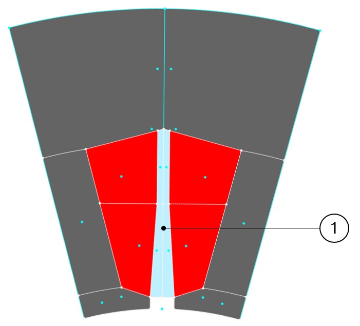
- Mechanical device to represent rivet for example
- Fluid area
- Hole or Slit
- Cooling hole
- Faces and regions of slots
This section contains a description of all the faces and regions defined and used in the slot model.
Each face is defined by a location point. The coordinates of these points are defined in a general coordinate system.
The point must be within the corresponding face for all the values of user input parameters. Each face has a label and a nature. The nature of faces defines the corresponding regions.
The physical properties of regions are linked to the materials that can be used to build them. The table below gives the physical properties of slots.
Figure 3. Physical properties of the slot regions and associated materials 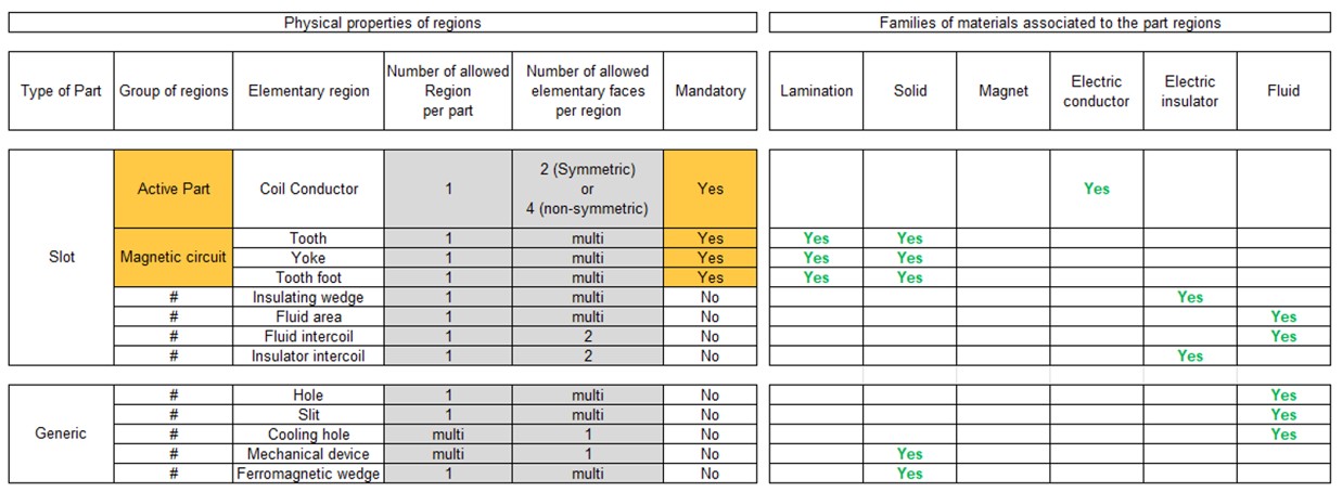
Note: When the regions are grouped (See group of regions above), the same material is associated with all the regions grouped.Note: The possible materials associated with the regions shown above can help users to see the meaning of elementary regions.