Skew
Type of skew
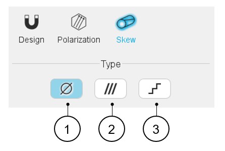
The design of the magnet can be considered with or without skewing. Hence, three
solutions are proposed:
- None: The magnet is not skewed.
- Continuous: The magnet is designed with continuous skewing.
- Step: The magnet is designed with step skewing.
 |
|
|---|---|
| 1 | Default setting: skew type is « None ». The magnet is not skewed. |
| 2 | Button to select a continuous skewed type of magnet. |
| 3 | Button to select a stepped skewed type of magnet. |
Continuous skew
 |
|
|---|---|
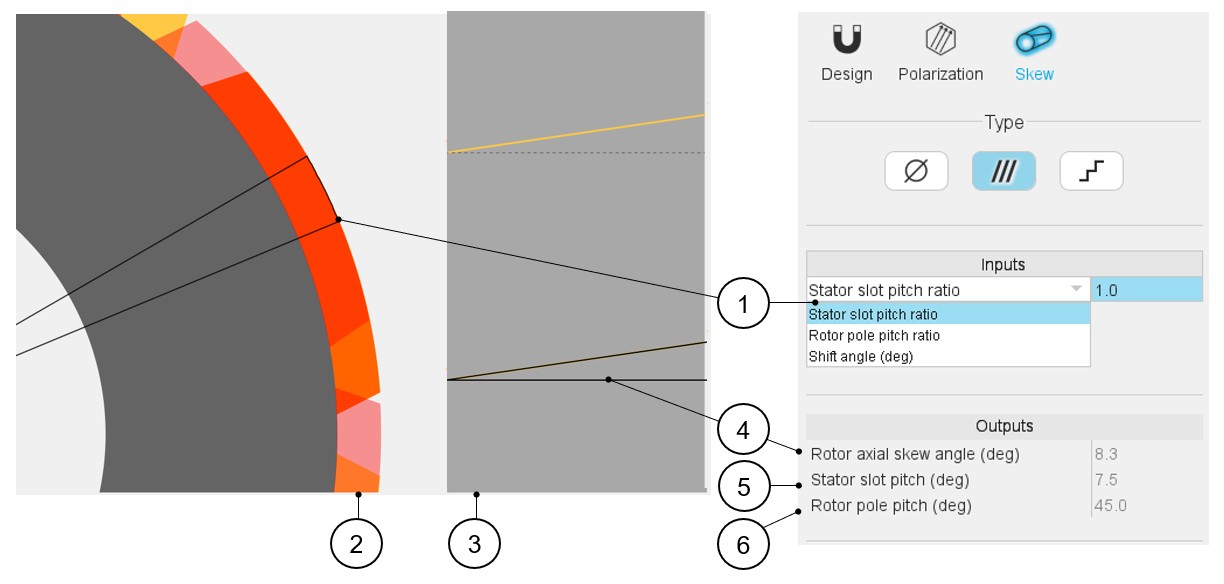
| 1 | Choose the definition mode of the skew: Three choices are
possible:
Note: whatever the definition mode is,
the resulting shift angle must be an element of [-180.0, 180.0]
(deg). |
| 2 | Visualization of the chosen skew angle on the machine radial view. |
| 3 | Visualization of the equivalent rotor axial skew angle on the machine-developed view. |
| 4 | Equivalent axial rotor angle (read only). |
| 5 | Equivalent stator slot pitch (read only). |
| 6 | Equivalent rotor slot pitch (read only). |
Note: The user can add a skew angle on the rotor or on the stator.
If a skew is already defined in the rotor when setting a skew on the stator, the
rotor skewing will be automatically reset to “None” and vice-versa.
Step skew
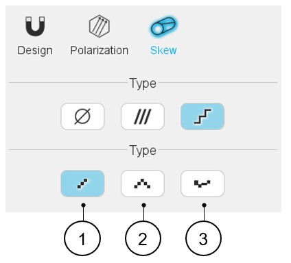
The design of the magnet can be considered with three kinds of step skew:
- Linear: Linear step skew definition mode.
- V Shape: V-shape step skew definition mode
- Custom: Custom step skew definition mode
 |
|
|---|---|
| 1 | Default setting: The step skew type is « Linear ». |
| 2 | Button to select the V-shape step skew type. |
| 3 | Button to select the Custom skew type. |
Note: The user can add a skew angle on the rotor (continuous or
step) or on the stator (continuous). If a skew is already defined in the stator when
setting a skew on the rotor, the stator skewing will be automatically reset to
“None” and vice-versa.
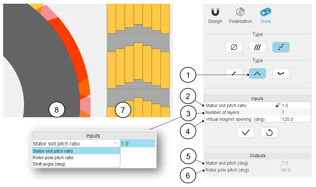
Linear step skew
 |
|
|---|---|
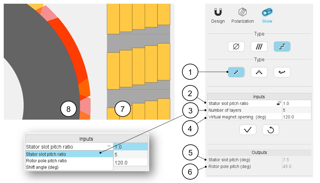
| 1 | Linear step skew definition mode |
| 2 | Choose the definition mode of the skew:
Note: whatever the definition mode
is, the resulting shift angle must be an element of [-180.0,
180.0] (deg). |
| 3 | Number of layers: it must be included in the range of [2;50]. |
| 4 | Virtual magnet opening to adjust the axial view to any size of magnet opening - It must be included in the range of ]0;180] degrees. |
| 5 | Equivalent stator slot pitch (read only) |
| 6 | Equivalent rotor slot pitch (read only) |
| 7 | Visualization of the machine-developed view resulting from the axial magnet angle, the number of layers and the virtual magnet opening. |
| 8 | Visualization of the chosen skew angle on the machine radial view. |
V shape step skew
 |
|
|---|---|
| 1 | V shape step skew definition mode |
| 2 | Choose the definition mode of the skew:
Note: whatever the definition mode
is, the resulting shift angle must be an element of [-180.0,
180.0] (deg). |
| 3 | Number of layers: it must be included in the range of [2;50]. |
| 4 | Virtual magnet opening to adjust the axial view to any size of magnet opening - It must be included in the range of ]0;180] degrees. |
| 5 | Equivalent stator slot pitch (read only) |
| 6 | Equivalent rotor slot pitch (read only) |
| 7 | Visualization of the machine-developed view resulting from the axial magnet angle, the number of layers and the virtual magnet opening. |
| 8 | Visualization of the chosen skew angle on the machine radial view. |
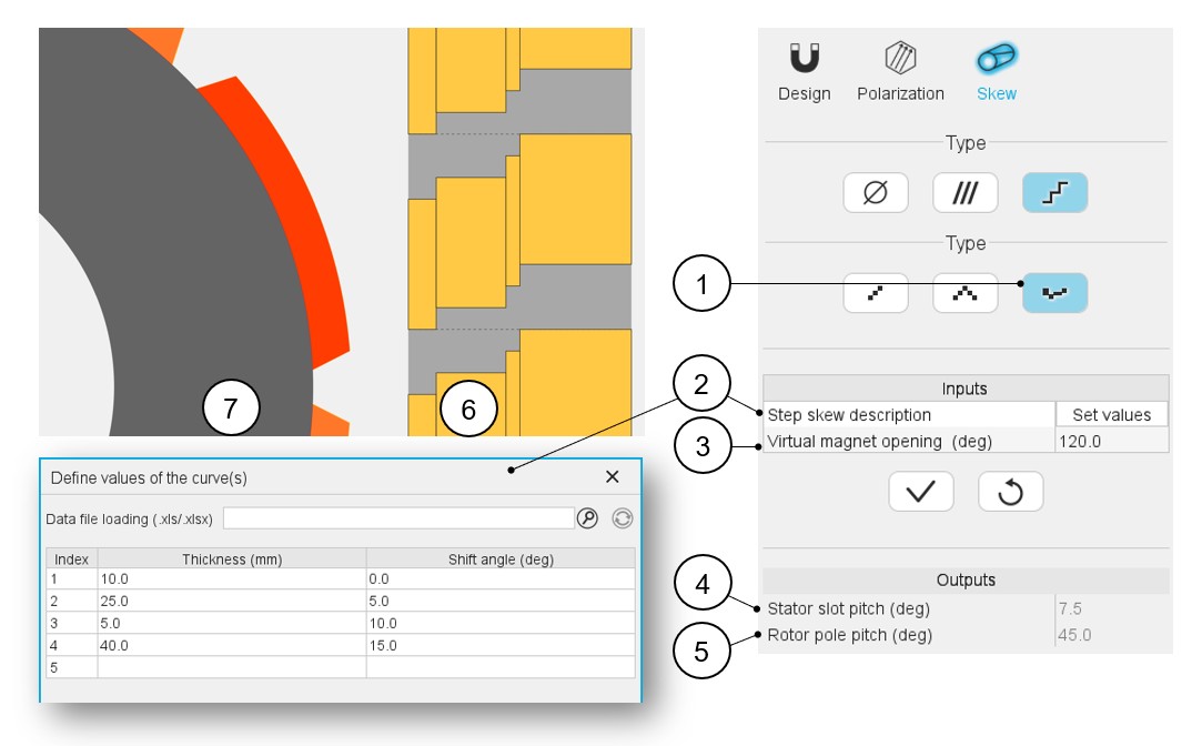
Customized step skew
 |
|
|---|---|
| 1 | Custom step skew definition mode. |
| 2 | Click on the button “Set values” of the field “Step skew description” to open a dialog box to define the custom step skew. Refer to the section that illustrates how to fill the Custom step skew table via the dedicated dialog box. |
| 3 | Virtual magnet opening to adjust the axial view to any size of magnet opening - It must be included in the range of ]0;180] degrees. |
| 4 | Equivalent stator slot pitch (read only). |
| 5 | Equivalent rotor slot pitch (read only). |
| 6 | Visualization of the machine-developed view resulting from the axial slot angle, the number of layers and the virtual magnet opening. |
| 7 | Visualization of the chosen skew angle on the machine radial view. |
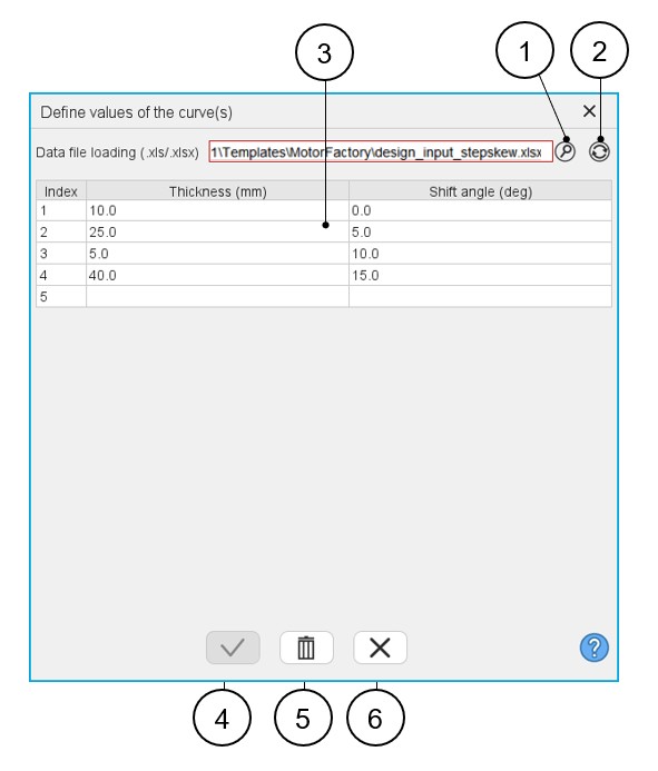
This section illustrates how to fill the customized step skew table via the dedicated dialog box.
Once clicking on the button “Set values” of the field “Step skew description” the following dialog box is opened.
 |
|
|---|---|
| 1 | Browse the folder to select an Excel file in which is described the custom step skew configuration. |
| 2 | Button to refresh the table data when the considered Excel file has been modified. |
| 3 | Fields to be filled with data to describe the step skew configuration to be considered. |
| 4 | Button to validate the inputs (Pressing the “enter key” twice applies inputs too). |
| 5 | Button to empty the table contents. |
| 6 | Button to close the dialog box. The last modifications are not considered. |
Note: The first value of the shift angle must be
“0”.
Note: The shift angle of each layer (or index)
refers to the reference axis given by the dash line in the axial view (position of
the first layer).
Note: The sum of the thickness of
each layer must be equal to the rotor length.