Design
Magnet topology
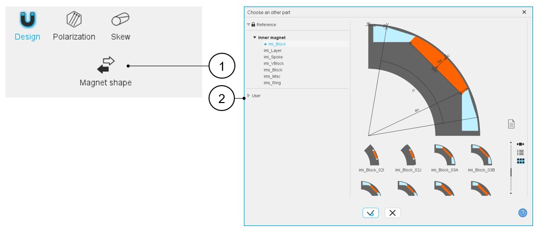
Choosing a new magnet topology is possible by clicking on the "Magnet shape" button. See the section “Choose part” for additional information. This opens a dialog box, allowing access to the magnet libraries.
It allows visualizing, comparing, choosing, and importing another magnet topology to modify in the current machine design.
 |
|
|---|---|
| 1 | Magnet shape button allows accessing the magnet libraries to change the magnet topology. |
| 2 | Dialog box to visualize and to select the topologies of magnets from the magnet part libraries. |
Inputs / Outputs
 |
|
|---|---|
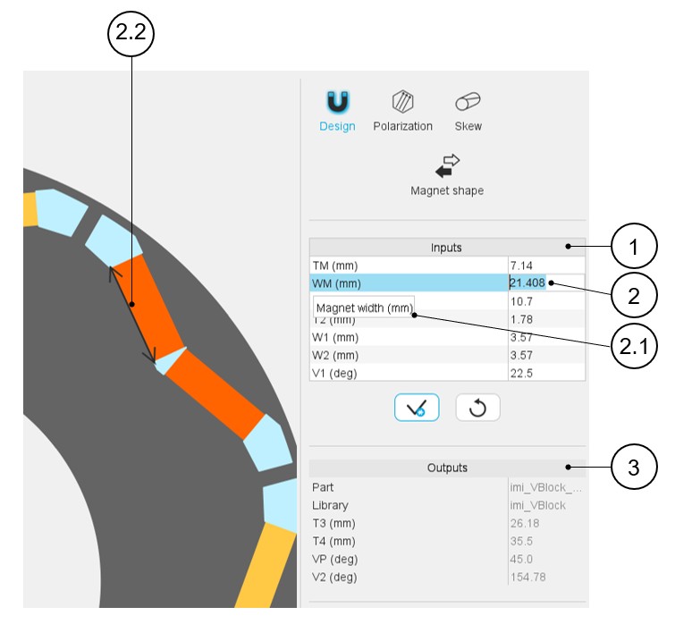
| 1 | User input parameter fields to enter the value. |
| 2 | Selecting a parameter highlights it. |
| 2.1 | Selecting a parameter displays the corresponding tooltip, which completes information about the parameter. |
| 2.2 | Select a parameter label that displays the corresponding arrow on the picture. |
| 3 | Output parameters (read only data) to complete the description of
the topology. Note: The name of the part and
its original library are mentioned in this
section. |
Magnet physical properties
- List of possible elementary regions for magnetsHere is an example of regions for an inner magnet.Note: The same principles apply to the outer magnet.
Table 3. Regions for inner magnet 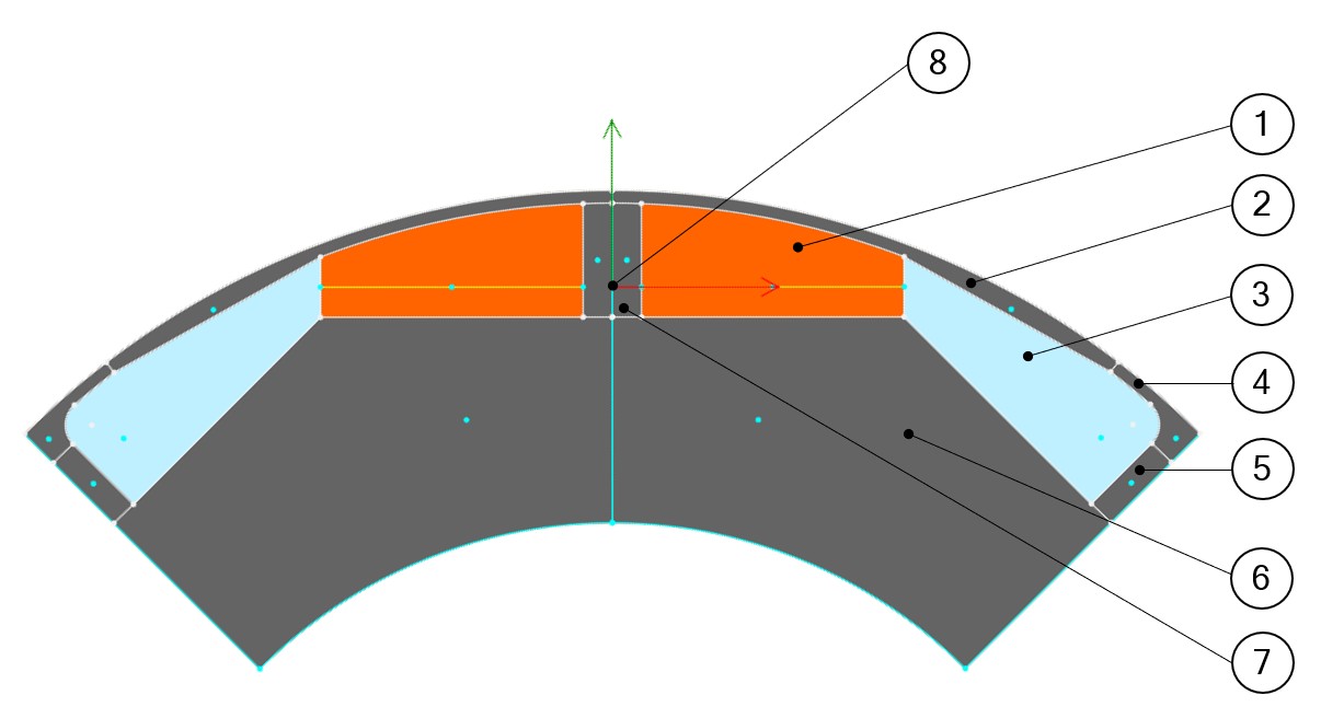
1 Magnet 2 Pole shoe 3 Edge 4 Bridge 5 Web 6 Yoke 7 Web 8 LOCAL coordinate system for defining the polarization of the magnet Note: A coordinate system is dedicated to magnets. This is what we call the LOCAL coordinate system. It is used to define the magnet’s polarization.- By default, a GLOBAL coordinate system is defined. Its reference point is located at the center of the rotor.
- For spoke magnets, the coordinate system defining polarization must be
along the symmetry axis. Otherwise, the polarization will not be
consistent.
Figure 1. Definition of the local coordinate system for spoke magnets 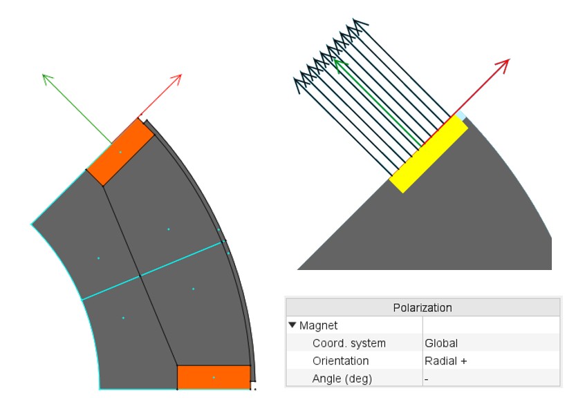
- Magnet, Pole shoe, Edge, Bridge, Web, Yoke (illustrated above).
- Pole core, Interpole or Hub
- Cooling hole
- Mechanical device to represent rivet for example
- Ferromagnetic wedge
- Hole or Slit
Figure 2. 1 – Example of slit 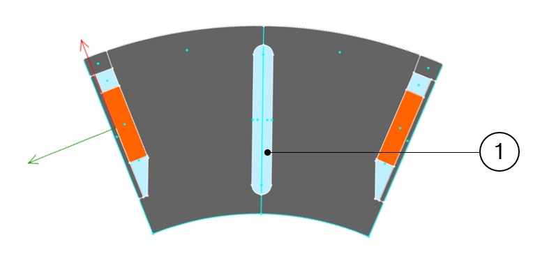
- Faces and regions of slots
This section contains a description of all the faces and regions defined and used in the magnet model.
Each face is defined by a location point. The coordinates of these points are defined in a general coordinate system.
The point must be within the corresponding face for all the values of user input parameters. Each face has a label and a nature. The nature of faces defines the corresponding regions.
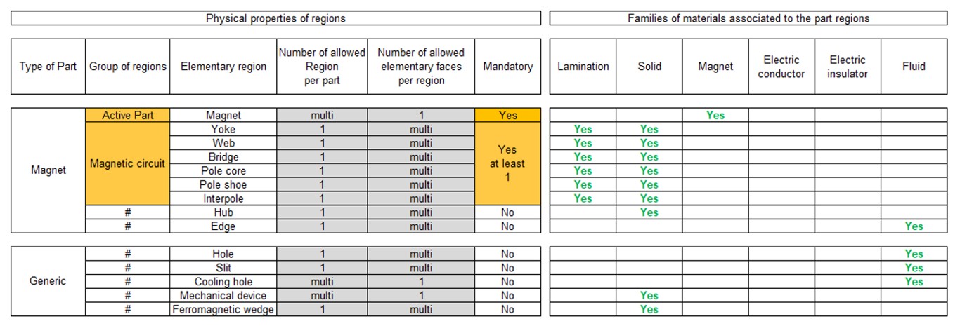
The physical properties of regions are linked to the materials that can be used to build them. The table below gives the physical properties of magnets.