Polarization
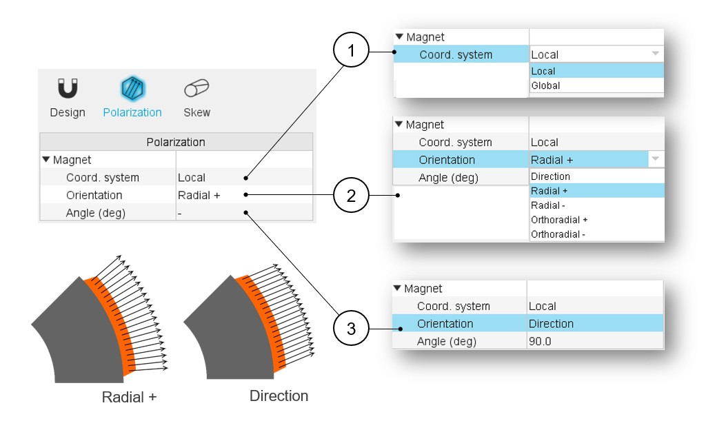
Type of polarization
 |
|
|---|---|
| 1 | Two coordinate systems are available:
Note: The reference axis (X-axis for
Cartesian coordinate system) has a red color. |
| 2 | Five strategies of polarization are proposed:
|
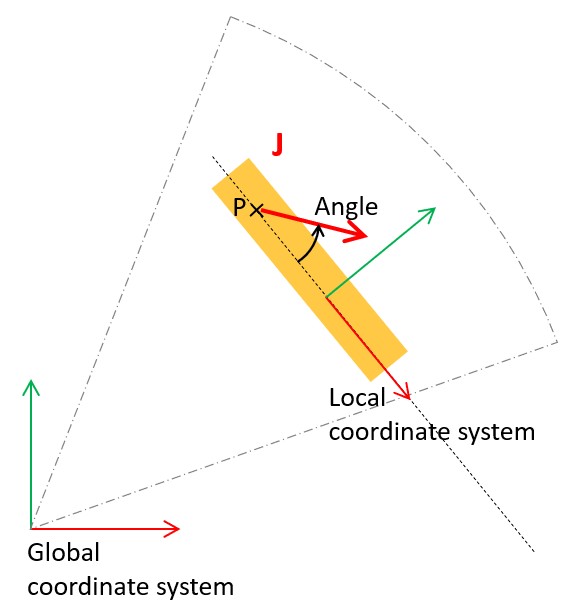
| 3 | Definition of the polarization angle with a Direction as a strategy of polarization. |
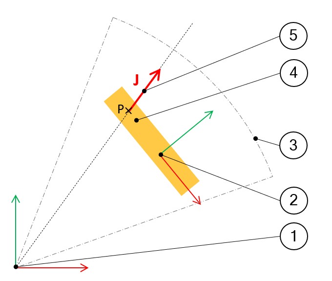
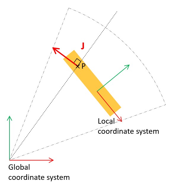
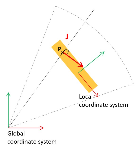
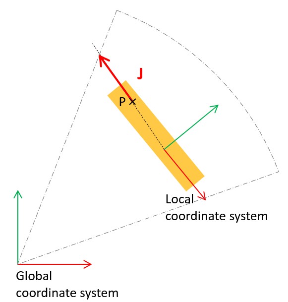
Polarization orientation illustrations
 |
|
|---|---|
| 1 | Global coordinate system. The origin is positioned at the rotor center. The reference axis is the X-axis. Its color is red. |
| 2 | Local coordinate system. Its location is defined for each magnet
topology. See the “Part Factory” application for more information. The reference axis is the X-axis. Its color is red. |
| 3 | Borders of the part sector in which magnet topology is defined. |
| 4 | Magnet in which point P is considered to illustrate the polarization orientation. |
| 5 | Polarization of the magnet considered at any point P. |
 |
 |
|
Polarization / Radial + Global coordinate system |
Polarization / Radial – Global coordinate system |
 |
 |
|
Polarization / Orthoradial + Global coordinate system |
Polarization / Orthoradial – Global coordinate system |
 |
 |
|
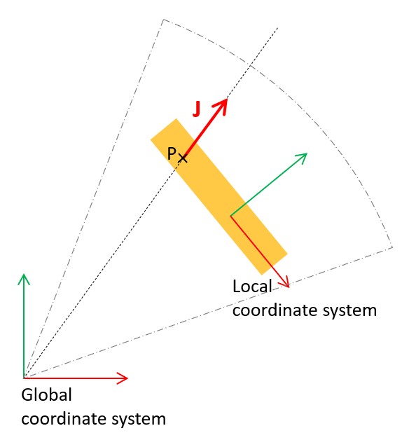
Polarization / Radial + Local coordinate system |
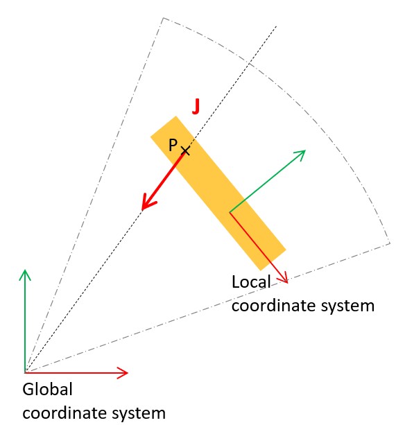
Polarization / Direction + Angle Local coordinate system |