Fluidic - Inputs
1. Overview
The tools available in the fluidic tab allow defining the parameters that drive the convection phenomenon cooling the frame:
- On the external surfaces of the frame and of the end caps
- In the cooling circuit, when a cooling circuit is defined by the user in the MACHINE subset, HOUSING panel, CIRCUIT setting.
Two choices are available to define the convection occurring on the external surface of the frame and of the end caps. Natural or Forced.
By default, Convection mode is set to “Natural”.
 |
|
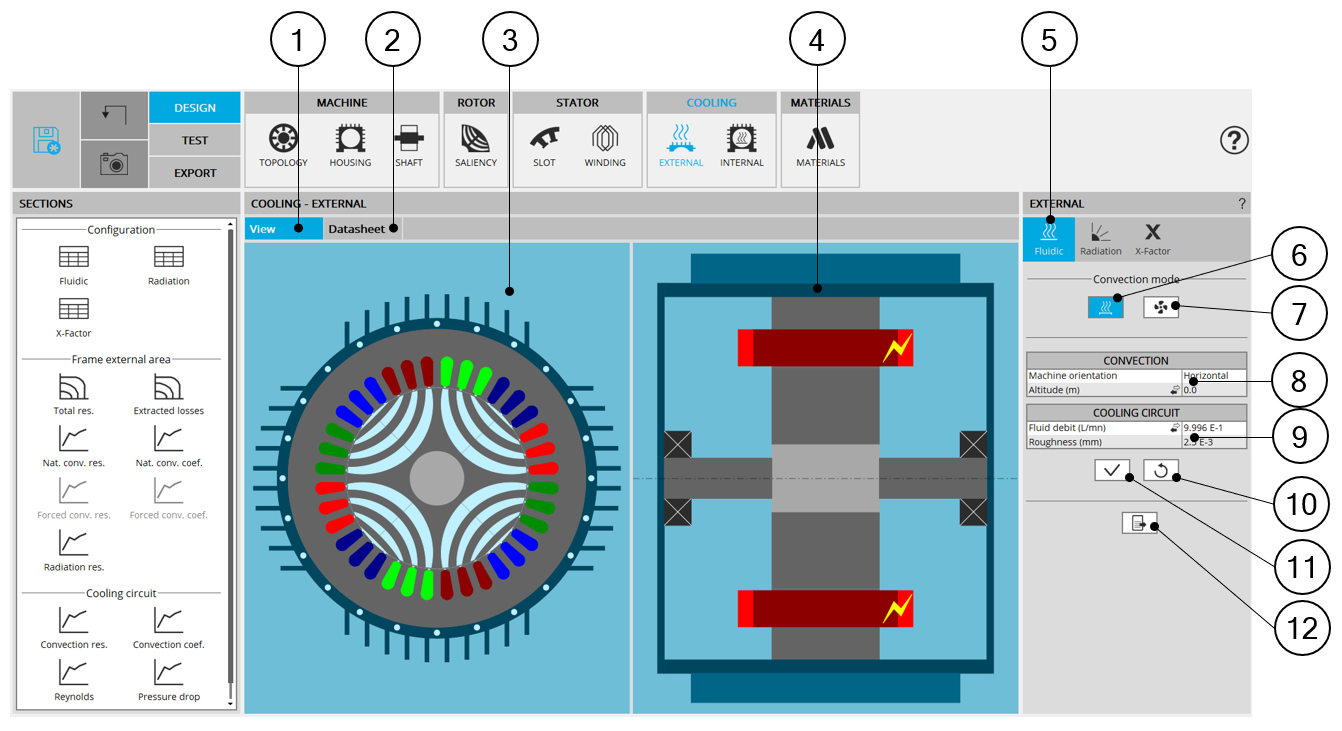
| External cooling - Fluidic design area | |
| 1 | Display the axial and radial view of the machine. |
| 2 | Display the external cooling datasheet, showing the main thermal parameters of the frame cooling. |
| 3 | Radial view of the motor, where specific exchange areas can be highlighted depending on the selected input. |
| 4 | Axial view of the motor, where specific exchange areas can be highlighted depending on the selected input. |
| 5 | The section fluidic is selected. |
| 6 | Selected button to set that the external areas of the frame and the end caps are cooled by natural convection (no forced fluid flow). |
| 7 | Selected button to set that the external areas of the frame and the end caps are cooled by forced convection (forced fluid flow around the machine). |
| 8 | Input related to the fluidic corresponding to the selected convection mode. |
| 9 | Input related to the cooling circuit when a cooling circuit exists. |
| 10 | Button to restore default input values. |
| 11 | Button to apply inputs. Pressing the enter key twice applies inputs too. |
| 12 | Icon to export external cooling data into *.txt or *.xlsx files. |
2. Natural convection
This convection mode corresponds to no forced fluid velocity around the machine. When selecting this mode, the only convection modeled is the fluid convection movement due to the difference of fluid temperatures (giving a difference of fluid density) close to the frame compared with the fluid far from the frame.
For instance, for a totally enclosed machine, cooled by natural convection in air, the frame will be hotter than the air close to it. This will warm the air surrounding the frame, feeding a natural « convective pump » due to the difference of air densities close and far from the frame (the hotter air having a lower density).
 |
|
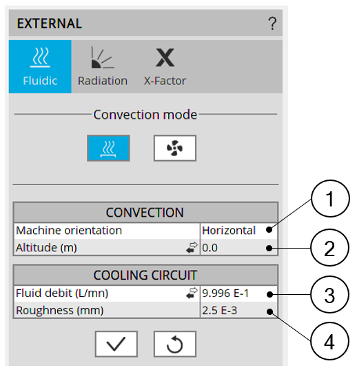
| Natural convection - Inputs | |
| 1 | Machine orientation. The resulting orientation can be seen in the axial view of the machine. The machine orientation has an impact only on the natural convection occurring on the external surface of the frame and the end caps |
| 2 | Altitude or Pressure (depending on the input mode selected by the user).
The pressure has an impact on the gas properties, changing the convection (natural and forced) occurring inside and outside the frame. This pressure can be set directly as a pressure, or as an altitude of use of the machine depending on the user choice. When selecting the altitude, an internal model computes the equivalent atmospheric pressure to consider for the convection computations. Note:
|
| 3 | Fluid debit or Fluid velocity (depending on the input mode selected by
the user). This input exists only when a cooling circuit has been defined by the user in the MACHINE subset, HOUSING panel, CIRCUIT setting. It corresponds to the fluid flow debit or velocity existing in the cooling circuit. This input will be considered for every thermal computation, including the tests (and not only for the model evaluation in the external cooling design environment). |
| 4 | The roughness of the cooling circuit pipe is only considered to compute the regular pressure losses in the cooling circuit and does not affect the computation of the temperatures. |
3. Forced convection
This convection mode allows adding forced convection in addition to the natural convection that always exists. When selecting this mode, the effect of the forced fluid flow around the machine is detailed separately of the natural convection in the results.
The resulting convection occurring on the machine is a mix of natural convection and forced convection.
 |
|
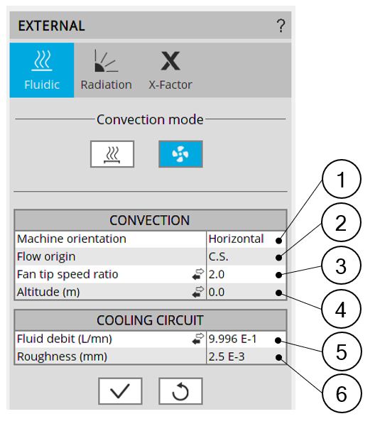
| Natural convection - Inputs | |
| 1 | Machine orientation. The resulting orientation can be seen in the axial view of the machine. The machine orientation has an impact only on the natural convection occurring on the external surface of the frame and of the end caps |
| 2 | Flow origin. This describes the origin of the fluid flow cooling the external surfaces of the frame and the end caps. The flow can come from the Connection Side or from the Opposite Connection Side. Arrows are displayed in the axial view of the machine to illustrate the user choice. |
| 3 | Fan tip speed ratio or Constant fluid speed or Forced convection
coefficient. (depending on the input mode selected by the user). This input describes the forced convection phenomenon existing on the outer surfaces of the frame and of the end caps. Please refer to additional information below. |
| 4 |
Altitude or Pressure (depending on the input mode selected by the user). The pressure has an impact on the gas properties, changing the convection (natural and forced) occurring in and out of the frame. This pressure can be set directly as a pressure, or as an altitude of use of the machine depending on the user choice. When selecting the altitude, an internal model computes the equivalent atmospheric pressure to consider for the convection computations. Note:
When the external or internal fluid is a liquid (meaning it is not a
gas), this input is ignored for the corresponding convection
phenomenon.
|
| 5 | Fluid debit or Fluid velocity (depending on the input mode selected by
the user). This input exists only when a cooling circuit has been defined by the user in the MACHINE subset, HOUSING panel, CIRCUIT setting. It corresponds to the fluid flow debit or velocity existing in the cooling circuit. This input will be considered for every thermal computation, including the tests (and not only for the model evaluation in the external cooling design environment). |
| 6 | Roughness: The roughness of the cooling circuit pipe is only considered to compute the regular pressure losses in the cooling circuit and does not affect the computation of the temperatures. |
 |
|
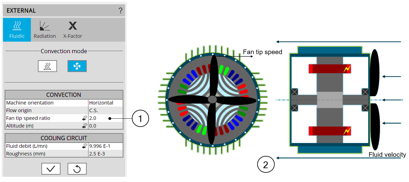
| Natural convection - Inputs | |
| 1 | Fan tip speed ratio or Constant fluid speed or Forced convection
coefficient. (depending on the input mode selected by the user). This input describes the forced convection phenomenon existing on the outer surfaces of the frame and of the end caps. The fan tip speed ratio describes the ratio between the fluid velocity and the tip speed of the rotor. This describes the behavior of a shaft mounted fan which rotation depends on the speed of the rotor. Then, when using this input, the external fluid velocity along the frame will be proportional to the rotation speed of the rotor |
| 2 | The user set the ratio between the fan blade tip speed (the tip of the
blades being considered at the frame external radius, without considering
the possible fins and the velocity of the fluid projected by the fan. The default value is 2. This corresponds to average fans, where the tip speed of the fan blade is two time higher than the average speed of the fluid projected by the fan. Lower this ratio will be, more efficient will be the cooling (because with a lower ratio, the coolant velocity will be higher at a given rotation speed of the rotor) Constant fluid speed input can be used to model a fixed coolant velocity, whatever the rotor speed is. It allows modeling an external cooling system blowing air on the machine without dependency of the machine. Forced convection coefficient input allows experts to directly force in the model a forced convection coefficient.This coefficient describes only the “forced” component of the convection. This forced convection set by the user will be added to the natural convection by an internal computation. The impact of the natural and forced components of the cooling can be seen in the outputs. |