Internal cooling
1. Overview
This step allows defining the thermal modeling of the internal cooling, meaning the complex thermal transfers occurring inside the machine.
This panel can be reached only when housing, a shaft and bearings are defined.
- The housing can be defined in the MACHINE subset, HOUSING panel, FRAME settings.
- The shaft can be defined in the MACHINE subset, SHAFT panel, and SHAFT settings.
- Bearings can be defined in the MACHINE subset, SHAFT panel, and BEARING settings.
 |
|
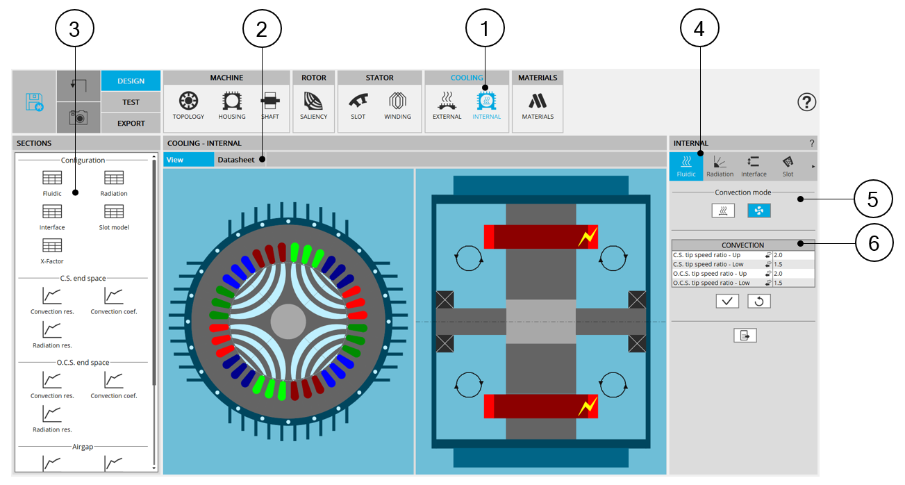
| INTERNAL COOLING design area - Overview | |
| 1 | Selection of the COOLING subset: INTERNAL panel (Click on the icon INTERNAL) |
| 2 | Once the internal cooling parameters are defined, corresponding results
are automatically displayed in form of datasheet. Visualization of the internal cooling characteristics (inputs, and corresponding results) is possible. Scrollbars allow browsing the whole document rapidly and having an overview of all the results. Using scrollbars, complete data can be accessed and visualized. |
| 3 | Shortcuts for displaying the corresponding chapter of the internal cooling datasheet. |
| 4 | Internal cooling settings allow describing the internal cooling parameters. |
| 5 | Choice of the internal convection mode: natural or forced. |
| 6 | Inputs defining the convection (forced or natural, corresponding to the choice above). |
2. Advices for use
2.1 Hypothesis on fluidic computations
Due to the hypothesis made in fluidic computations, some non-continuity can be observed in the fluid convection coefficient evolution, especially in the airgap and on the frame. These non-linearities and possible non-continuities are related to the change from laminar to turbulent fluid flow.
2.2 Validity domain of the fluidic computations
The fluidic computation embedded in FluxMotor uses analytical laws. For some specific fluid properties, extreme temperatures, and very low forced cooling velocity, the computation can be out of this validity domain.
In such cases, some errors will occur, asking to check the fluid properties, and the velocity involved in the forced convection.
For advanced usages, not covered by our hypothesis on fluid flow, it is advised to set a “user convection coefficient” manually for these specific regions.
2.3 Natural convection on end windings
When choosing to model that the end spaces are cooled with natural convection, FluxMotor model uses a quite low rotor tip speed ratio (a value of 5) to describe the fluid velocity far from the rotating components.
This can lead to overestimates the cooling of the end winding on high-speed machines. This model will be improved for future versions.
When a tip speed ratio of 5 seems to overestimate the end winding cooling, it is advised to switch to forced convection mode.
This mode allows forcing some higher tip speed ratios for areas far from the rotor, this reducing the efficiency of the cooling on the end winding.
2.4 Temperatures considered for fluidic computations
Some fluidic computations are based on two different temperatures: the temperature of the fluid, and the temperature of the wall from where the convection occurs.
This explains that the convection results shown in the design environment can be slightly different from the results obtained in the test environment.
In the design environment, the fluid and the wall are at the evaluation temperature, but in the test the wall and the fluid temperatures are evaluated during the solving and are different in most of the cases.
2.5 Interface thickness usage
The temperatures obtained on a machine highly depend on the interface thicknesses set between each part of the machine. The default interface gap values are set to correspond to classical existing values.
However, keep in mind that the temperatures seen on a real design will deeply depends on the interface qualities, linked to the quality of the mounting process.
Especially, for machines with high density of losses and efficient cooling systems, like water jacket cooled machines, the interface thickness between the frame and the stator yoke is one of the main thermal resistances in the heat extraction. The user must be very careful on the value used for this interface thickness.
The thermal resistances corresponding to the interface thicknesses are computed considering that the interfaces are made of air at 273.15 Kelvin, and at the atmospheric pressure at sea level, 1.013E5 Pa.
2.6 Radiation from the shaft
No radiation is considered from the shaft in our model.