X-Factors
1. Illustration of X-Factor mapping
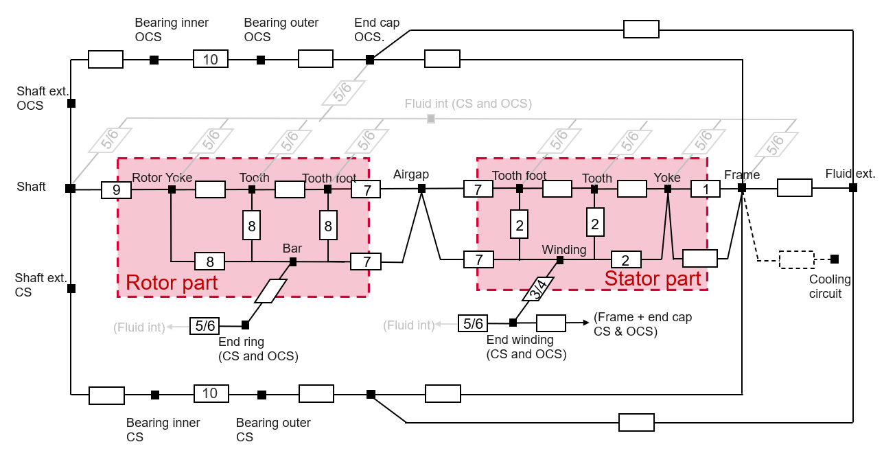
The following picture gives an example of a simple thermal circuit, including the main resistances corresponding to the default induction machine, where a frame, a shaft and bearings have been added.
The numbers on every resistance show what X-factor impacts this resistance value.
To keep the scheme simple, the radiation resistances are not represented there.
 |
 |
| Thermal circuit – Relation with the calibration factors |
2. Introduction
The X-Factor panel allows the user to defined calibration factors to tune the thermal modeling on specific resistances.
The calibration factors set in this panel are considered in the results shown in COOLING subset, INTERNAL panel environment, and in the TEST environment.
The X-Factor panel also contains a set of parameters defining the internal cooling (coolants temperature and rotor speed) allowing the user to evaluate the thermal model embedded.
The effect on every X-Factor value can be directly seen in the outputs displayed in internal cooling panel.
 |
|
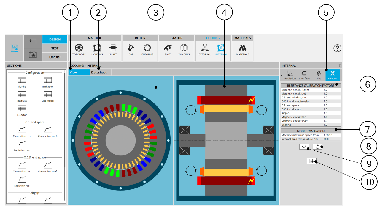
| Internal cooling – X-Factor design area | |
| 1 | Display the axial and radial view of the machine. |
| 2 | Display the internal cooling datasheet, showing the thermal parameters defining the internal heat exchanges. |
| 3 | Radial view of the motor, where specific exchange areas can be highlighted depending of the selected input. |
| 4 | Axial view of the motor, where specific exchange areas can be highlighted depending of the selected input. |
| 5 | The section X-Factors is selected. |
| 6 | Table of the calibration factors allowing the user to tune the thermal
modeling. Each X-factor tunes a set of resistances. The mapping showing the impact of each X-factor is explained in the below dedicated section. |
| 7 | Input table used for the evaluation of the internal cooling, defining the results displayed in the internal cooling datasheet. |
| 8 | Button to restore default input values. |
| 9 | Button to apply inputs. Pressing the enter key twice applies inputs too. |
| 10 | Icon to export internal cooling data into *.txt or *.xls files. |
 |
|
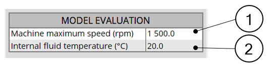
| External cooling – Model evaluation input table | |
| 1 |
Machine maximum speed. It is the maximum rotation speed for which the convection curves will be evaluated in the internal cooling datasheet. |
| 2 |
Internal fluid temperature It is the temperature used in internal cooling panel to evaluate the convection and the radiation occurring inside the machine. All the results shown in internal cooling panel used this temperature as the temperature of the internal fluid enclosed in the machine. Most of the curves shown in Internal cooling panel are plotted for a range of temperature going from this reference temperature to 150 Kelvin above it. Note: This temperature is only used for the model
evaluation in the internal cooling panel. This temperature does not
affect the test computations, where the internal fluid temperature is
found by the non linear solving during the solving of the test.
|
3. X-factor mapping
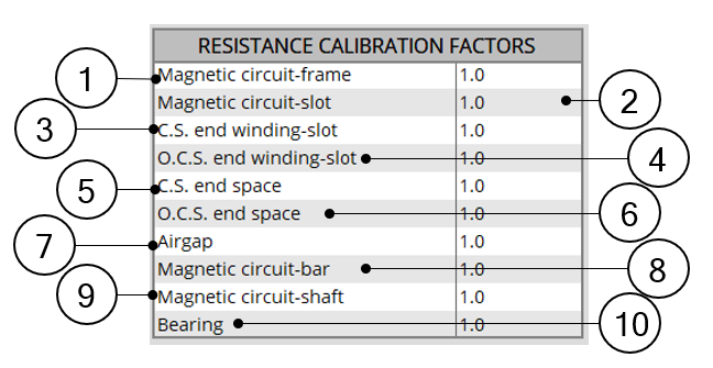
Each X-factor impacts a specific set of resistances, among the most important thermal resistances of the thermal modeling of a machine.
 |
|
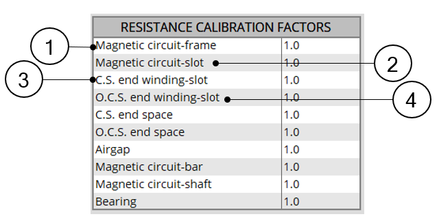
| Internal cooling – Calibration factors input table – Part 1 | |
| 1 |
Magnetic circuit-frame. This calibration factor tunes the total resistance between the stator yoke and the frame. This total resistance is composed of two resistances in series: · The conduction through the stator yoke until its border, computed by finite elements · The conduction through the imperfect interface between the stator magnetic circuit and the frame |
| 2 |
Magnetic circuit-slot. This calibration factor tunes each of the thermal resistances linking the stator core to the winding. Each of these resistances consists of several resistances in series: · The conduction through the stator core until the slot border, computed by finite elements · The conduction through the imperfect interface between the magnetic circuit and the liner · The conduction through the slot (using the equivalent conductivity defined in the settings “Slot model” of the “Internal cooling” panel. |
| 3 |
Connection Side end winding – slot. This calibration factor tunes the conduction resistance between the slots (meaning In-slot winding) to the Connection Side end winding. |
| 4 | Opposite Connection Side end winding – slot. This calibration factor tunes the conduction resistance between the slots (meaning In-slot winding) to the Opposite Connection Side end winding. |
 |
|
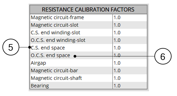
| Internal cooling – Calibration factors input table – Part 2 | |
| 5 |
Connection Side end space. This calibration tunes all the resistances involved in thermal exchanges with or through the Connection Side end space fluid: · The thermal resistances from each part composing the stator and the rotor to the Connection Side end space fluid (each of these resistances being composed of conduction through the machine depth added to convection at the rotor and stator ends) · The convection resistance between the Connection Side end winding and the Connection Side end space fluid. · The thermal resistance between the Connection Side end space fluid and the frame and end cap surfaces on the Connection Side. · The radiation resistances from the stator end, rotor end, and end winding, to the frame and the end cap surfaces on the Connection Side. |
| 6 |
Opposite Connection Side end space. This X-factor tunes every resistance involved in thermal exchanges with or through the Opposite Connection Side end space fluid: · The thermal resistances from each part composing the stator and the rotor to the Opposite Connection Side end space fluid (each of these resistances being composed of conduction through the machine depth added to convection at the rotor and stator end) · The convection resistance between the Opposite Connection Side end winding and the Opposite Connection Side end space fluid. · The thermal resistance between the Opposite Connection Side end space fluid and the frame and end cap surfaces on the Opposite Connection Side. · The radiation resistances from the stator end, rotor end, and end winding, to the frame and the end cap surfaces on the Opposite Connection Side. |
 |
|
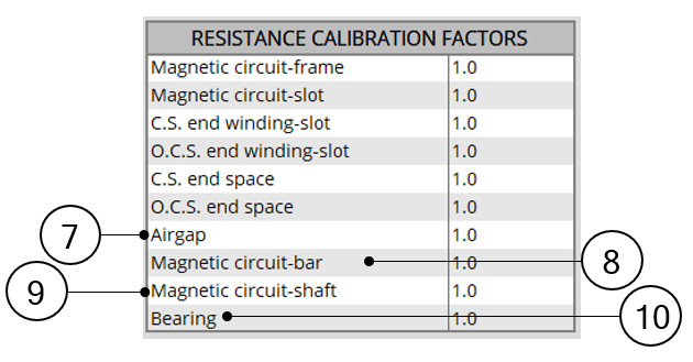
| Internal cooling – Calibration factors input table – Part 3 | |
| 7 |
Airgap. This calibration factor tunes every resistance involved in thermal exchanges with or through the airgap fluid: · The conduction through the stator yoke and slot until the airgap border, computed by finite elements · The conduction through the rotor yoke and magnets until the airgap border, computed by finite elements · The convection from the airgap border to the airgap fluid. · The radiation from every rotor component having a border along the airgap, to every stator component having a border along the airgap |
| 8 |
Magnetic circuit-bar. For every existing bar, this calibration factor tunes the total resistance existing between this bar and every component of the rotor magnetic circuit around it. Each of these resistances are composed of three resistances: · The conduction through the rotor yoke until the bar border, computed by finite elements · The conduction through the imperfect interface between the rotor magnetic circuit and the considered bar. · The conduction through the bar until its border, computed by finite elements |
| 9 |
Magnetic circuit-shaft. This calibration factor tunes the total resistance between the rotor yoke and the shaft. This total resistance is composed of two resistances in series: · The conduction through the rotor yoke until its border, computed by finite elements · The conduction through the imperfect interface between the rotor magnetic circuit and the shaft |
| 10 |
Bearings. This calibration factor tunes the resistances existing across the Connection Side bearing and the Opposite Connection Side bearing. These resistances are the resistances computed directly from the bearing equivalent airgap thickness set by the user in INTERFACE settings. |
The following picture gives an example of a simple thermal circuit, including the main resistances corresponding to the default induction machine, where a frame, a shaft and bearings have been added.
The numbers on every resistance show what X-factor impacts this resistance value.
To keep the scheme simple, the radiation resistances are not represented there.
|
|
|
|
| Thermal circuit – Relation with the calibration factors |