Interface gaps - Inputs
Interface gaps - Inputs
This panel allows describing imperfect contacts between the different components of the machine.
The imperfect contacts are here modeled as a parasitic airgap between two parts, through which the heat must be conducted through to go from one part to the other.
The interface gaps are composed of air at the atmospheric pressure, at 20 °C, equivalent to 293.15K. For more information on material properties, please refer to FluxMotor material database (“Materials application”).
Mainly, the imperfect contacts existing in a machine are:
-
Each interface/mounting of a laminated part on a solid material
Between the magnetic circuit and the frame
Between the magnetic circuit and the bar
Between the magnetic circuit and the shaft
-
The imperfect contact between the magnetic circuit and the liner surrounding the slot.
- The imperfect contact between the frame (straight part) and the two end caps
-
The bearings: An interface gap thickness is used to compute the thermal resistance of each bearing. These values of contact thickness are used in computations for both bearings (Connection Side and Opposite Connection Side).
 |
|
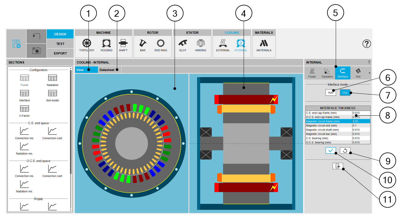
| Internal cooling - Interface design area | |
| 1 | Display the axial and radial view of the machine. |
| 2 | Display the internal cooling datasheet, showing the thermal parameters defining the internal heat exchanges. |
| 3 | Radial view of the motor, where specific exchange areas can be highlighted depending of the selected input. |
| 4 | Axial view of the motor, where specific exchange areas can be highlighted depending of the selected input. |
| 5 | The section “Interface” is selected. |
| 6 | Button to set the interface gaps automatically by internal process. |
| 7 | Selected button, to set user interface gaps. |
| 8 |
Parasitic interface thicknesses corresponding to the selected interface mode. In user mode, the following thicknesses must be set:
This corresponds to the imperfect contact between the liner and the iron core.
|
| 9 | Button to restore default input values. |
| 10 | Button to apply inputs. Pressing the enter key twice applies inputs too. |
| 11 | Icon to export internal cooling data into *.txt or *.xls files. |