Fluidic - Inputs
1. Introduction
The tools available in the fluidic tab allow defining the parameters that drive the convection phenomenon in the end spaces, involving the surfaces of the frame (internal surface), the end cap (internal surface), the shaft, the rotor and stator ends, and the end winding or potting.
Two choices are available to define the convection occurring on the external surface of the frame and of the end caps. Natural or Forced.
By default, Convection mode is set to “Natural”.
 |
|
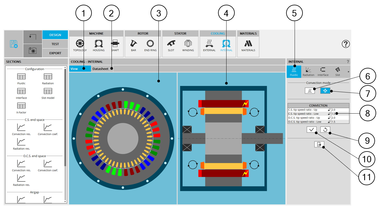
| Internal cooling - Fluidic design area | |
| 1 | Display the axial and radial view of the machine. |
| 2 | Display the internal cooling datasheet, showing the thermal parameters defining the internal heat exchanges. |
| 3 | Radial view of the motor, where specific exchange areas can be highlighted depending of the selected input. |
| 4 | Axial view of the motor, where specific exchange areas can be highlighted depending of the selected input. |
| 5 | The section “Fluidic” is selected. |
| 6 | Selected button to set that natural convection occurs in the end spaces (no specific fluid flow modeled in addition to the rotation of the machine). |
| 7 | Selected button to set that forced convection occurs in the end spaces (a specific fluid flow on each area of the end caps can be specify by the user, that can be linked to the machine rotation speed or not). |
| 8 | Input related to the fluidic corresponding to the selected convection mode. |
| 9 | Button to restore default input values. |
| 10 | Button to apply inputs. Pressing the enter key twice applies inputs too. |
| 11 | Icon to export internal cooling data into *.txt or *.xls files. |
2. Natural convection
This convection mode models that no specific forced fluid flow exists in the end caps in addition to the natural fluid movement induced by the machine rotation speed.
The modeled convection exchanges, corresponds to the sum of two phenomena:
-
The differences of fluid temperature existing in different volumes of the end spaces (giving a difference of fluid density) creating some fluid natural swirling in the end spaces.
-
The fluid movement induced by the rotation speed of the machine.
The internal natural convection model is based on classical correlations for end spaces, considering different fluid velocities for the parts close to the rotating parts, and far from the rotating parts.
Therefore, there is no user input to define in this mode.
 |
|
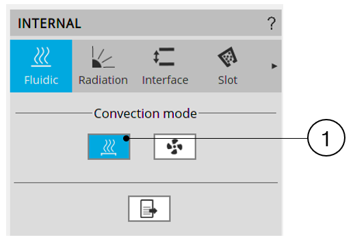
| Natural convection - Inputs | |
| 1 | Natural convection mode is selected. In this mode, there is no input to define. |
3. Forced convection
This convection mode allows forcing the convection model used for every region of the end spaces.
It can be used to model:
-
Increased convection effects due to rotor fins of shaft mounted internal fans.
-
A fan internally forcing constant ventilation whatever the rotation speed of the machine.
-
Some forced convection coefficients in the end spaces.
The end spaces are divided in four areas, corresponding to four inputs the user must defined in forced convection mode:
-
The « Upper » Connection Side region, corresponding to the Connection Side convection areas far from the rotating parts.
-
The « Lower » Connection Side region, corresponding to the Connection Side convection areas close to the rotating parts.
-
The « Upper » Opposite Connection Side region, corresponding to the Opposite Connection Side convection areas far from the rotating parts.
-
The « Lower » Opposite Connection Side region, corresponding to the Opposite Connection Side convection areas close to the rotating parts.
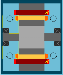
When selecting one of these four inputs, the corresponding exchange areas are highlighted in the axial view of the machine.
See below illustrations.
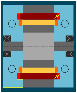 |
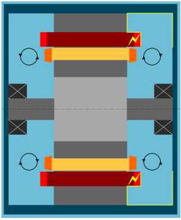 |
| Opposite Connection Side “Upper” region – far from the rotor | Connection Side “Upper” region – far from the rotor |
 |
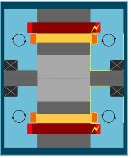 |
| Opposite Connection Side “Lower” region – close to the rotor | Connection Side “Lower” region – close to the rotor |
For all the four represented regions, the convection can be modeled with three different input ways:
-
A tip speed ratio
-
A fluid speed
-
A convection coefficient
The user can select the inputs mode of each region using the dedicated arrow or clicking on the input mode to change.
 |
|
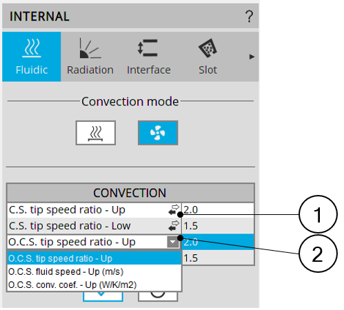
| Forced convection – Selection of input modes | |
| 1 | Click on the arrow, or directly on the input mode, to show the drop-down menu allowing the input mode selection |
| 2 | Drop down menu allows choosing an input mode for the dedicated convection region. |
The « Tip speed ratio » input mode allows setting a fluid velocity proportional to the rotor tip speed.
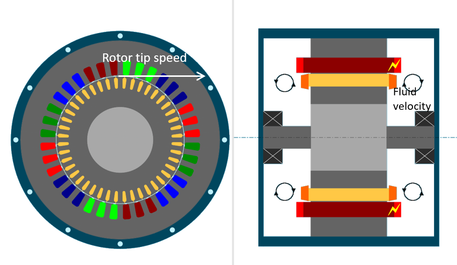 |
| Definition of the fluid velocity proportional to the rotor tip speed |
This can be used to model a shaft mounted fan, of rotor fins.
The default values of tip speed ratios are 2 for the regions far from the rotor.
A tip speed ratio of 2 for an « Upper » region (meaning a region far from the rotor) corresponds to a shaft mounted fan, or rotor fins, that blows air to this region with an average efficiency.
For « Upper » region of a side without fan or fins, it is advised to set a rotor tip speed ratio of 5. This corresponds to the FluxMotor natural convection model.
The default value of tip speed ratio is of 1.5 for the regions close to the rotor.
In fact, for these regions, the considered fluid speed is the relative speed between the fluid velocity and the rotating parts speed, meaning that in these regions the convection is highly related to the rotation speed.
The « Constant fluid speed » input mode can be used to model a constant ventilation speed.
The «Convection coefficient » input mode allows directly forcing a convection coefficient in the corresponding region.
-
For any chosen input mode, the end spaces are considered as totally enclosed. No fluid exchange exists between the end space fluid (the « internal fluid ») and the « external fluid ».
The cooling strategy corresponding to blow an external fluid at a fixed temperature into and through the machine cannot be modeled in the current version of FluxMotor.
-
In both input modes « Tip speed ratio » and « Constant fluid speed », the fluid speed is applied to classical correlations depending on the nature of the sub region (end winding, frame, rotor part…).
In the « Convection coefficient » input mode, the same convection coefficient is applied in all sub regions (end winding, rotor end, end cap, frame…) of the regions for which the coefficient is chosen.
 |
|
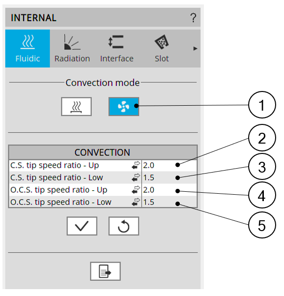
| Forced convection - Inputs | |
| 1 | Forced convection mode is selected |
| 2 | Input related to the Connection Side “Upper” region, here set as a tip speed ratio |
| 3 | Input related to the Connection Side “Lower” region, here set as a tip speed ratio |
| 4 | Input related to the Opposite Connection Side “Upper” region, here set as a tip speed ratio |
| 5 | Input related to the Opposite Connection Side “Lower” region, here set as a tip speed ratio |