Test No. VNL07 Find total or partial beam
separation/slippage depending on the applied loads.
Definition
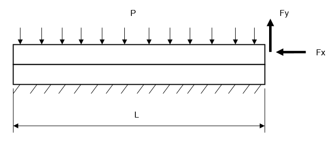
Two similar beams with dimensions 10 x 10 x 100 mm are in contact (Figure 1).
The material properties are:
Properties
Value
Friction Coefficient
Modulus of Elasticity
2.1e+11 Pa
Poisson's Ratio
0.3
Figure 1.
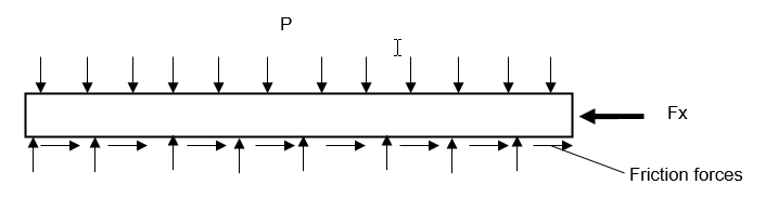
Five load cases are considered. In all load cases the lower beam bottom is fixed, the
upper beam is loaded on its top with total vertical load of 2 N uniformly
distributed over the surface. The right end of the upper beam is loaded either with
vertical load or with horizontal load uniformly distributed over the surface.
Table 1.
Load Case
Fx, [N]
Fy, [N]
1
0
1
2
0
0.9
3
0.3
0
4
0.31
0
5
0.29
0
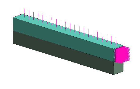
Beams were simulated as two solids (Figure 2). Contact condition at the
connection was set to "Separating" with friction coefficient
0.15.
Figure 2.
Results
Case 1:
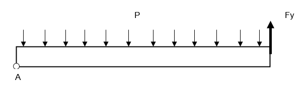
Figure 3. Figure 4.
Consider the equilibrium of the upper beam. If =0, then force N is equilibrated by the
reaction force in contact. As grows, the beam deforms, and the contact
separation starts at its right end and expands to the left. Ultimately,
the contact fully separates and contact area degenerates into a line
(point A in Figure 3). The value of force which results in full separation can be
found from moments equilibrium equation.
This ultimate value is =1 N.
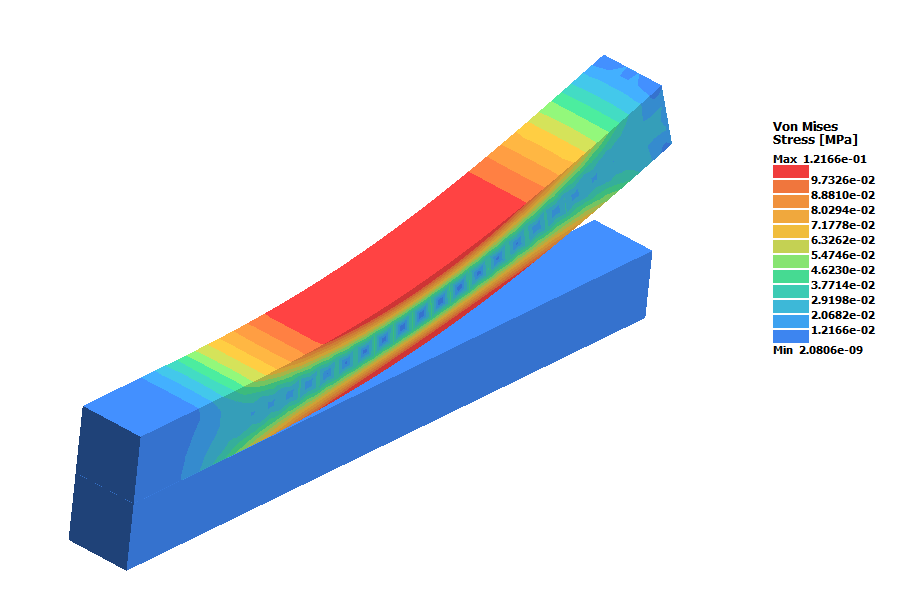
SimSolid result for this value of is shown in Figure 4. Full separation occurred and the
contact occurs only along the single edge which causes stress
concentration at the beam corner.
Case 2:
In this load case, force =0.9 N is not sufficient to cause full
separation of the contact (Figure 5).Figure 5.
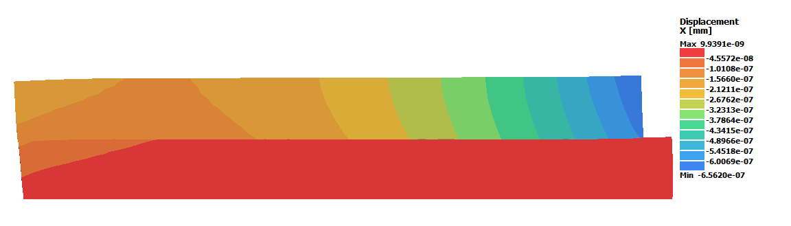
Case 3:
Figure 6. Figure 7.
In this load case, normal separation does occur because there is no
detaching force - =0. Shear force tends to cause beam slippage which is
resisted by friction forces distributed over the contact area. In
equilibrium the force projects onto the horizontal axis:
Where, is total friction force.
Maximum
total friction force is:
Total slippage (or total tangential separation)
starts when . When , only partial slippage is possible.
Maximum total friction force is .
The result for =0.3 N is shown in Figure 9. Full slippage develops in contact
area, but left lower edge of the upper beam is still almost coincides
with the edge of the lower beam.
Case 4:
In this load case the shifting force is increased to 0.31 N. The force
exceeds the maximum friction force and the upper beam not only deforms
but also starts moving as a rigid body.Figure 8.
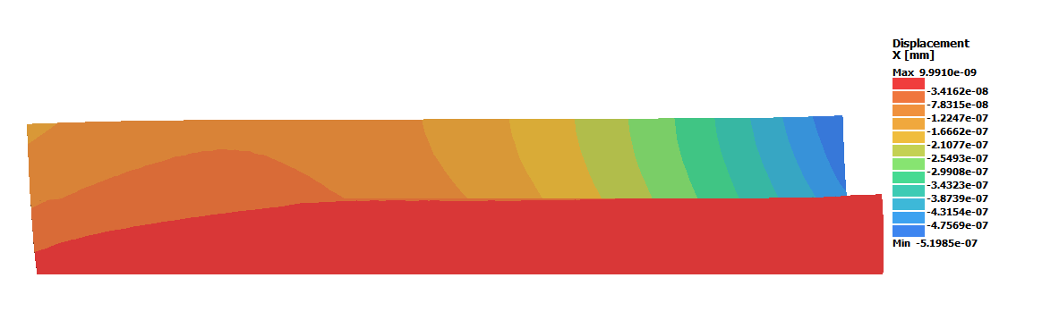
Case 5:
In this load case the shifting force is decreased to 0.29 N in order to not
exceed the maximum friction force. Only partial slippage occurs in this
case. There is a clear "sticking" contact area at the left end of the
beams.Figure 9.