Joints
Connect faces/spots that can have relative motion in the form of displacements and/or rotations.
- In the Project Tree, open the Connections workbench
-
On the Connections workbench, select
 > Joints.
-
In the Virtual connector dialog, create one of the
following types of joints:
Type Process Ball 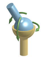
A ball joint allows free rotations in any direction about the joint center, while the translations are fully constrained. - Select the Ball radio button.
- Use the radio buttons to apply to either
Faces or
Spots.Note: If applying to Spots, you can choose to Create new spot.
- The joint center is set in COG by default. To change the joint center, clear the Set in COG check box and specify values for the X, Y, and Z coordinates.
Hinge 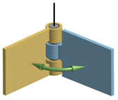
A hinge joint only allows rotations about the joint axis. The axis is defined by the joint center and a vector. - Select the Hinge radio button.
- Use the radio buttons to apply to either
Faces or
Spots.Note: If applying to Spots, you can choose to Create new spot.
- The joint center is set in COG by default. To change the joint center, clear the Set in COG check box and specify values for the X, Y, and Z coordinates.
- Specify the Joint axis in the X, Y, and Z fields.
Cylinder 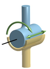
A cylindrical joint allows rotations about the joint axis and sliding along the axis. The axis is defined by the joint center and a vector. - Select the Cylinder radio button.
- Use the radio buttons to apply to either
Faces or
Spots.Note: If applying to Spots, you can choose to Create new spot.
- In the modeling window, select where to apply the joint.
- The joint center is set in COG by default. To change the joint center, clear the Set in COG check box and specify values for the X, Y, and Z coordinates.
- Specify the Joint axis in the X, Y, and Z fields.
Linear Guide 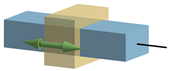
A linear guide joint only allows sliding along the joint axis. The axis is defined by the joint center and a vector. - Select the Linear guide radio button.
- Use the radio buttons to apply to either
Faces or
Spots.Note: If applying to Spots, you can choose to Create new spot.
- In the modeling window, select where to apply the joint.
- The joint center is set in COG by default. To change the joint center, clear the Set in COG check box and specify values for the X, Y, and Z coordinates.
- Specify the Joint axis in the X, Y, and Z fields.
Universal 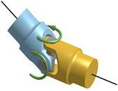
A universal joint allows rotary motion transmission between two shafts which are at an angle to each other and which have intersecting axes. The joint works as a ball joint but makes dependent shaft rotations about their axes. This joint requires definition of a joint center and axis of the both the shafts connected.
- Select the Universal radio button.
- Use the radio buttons to apply to either
Faces or
Spots.Note: If applying to Spots, you can choose to Create new spot.
- In the modeling window, select where to apply the joint.
- The joint center is set in COG by default. To change the joint center, clear the Set in COG check box and specify values for the X, Y, and Z coordinates.
- Use the radio buttons to specify Joint axes data for Axis 1 and Axis 2.
Flexible Shaft 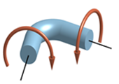
A flexible shaft allows complete rotary motion transmission between the two shafts. The joint works by constraining the rotations about the shaft axes. This joint requires definition of flexible-shaft end coordinates and respective shaft axes.
- Select the Flexible shaft radio button.
- Use the radio buttons to apply to either
Faces or
Spots.Note: If applying to Spots, you can choose to Create new spot.
- In the modeling window, select where to apply the joint.
- Use the radio buttons to specify Flexible shaft data for End 1 and End 2 coordinates.
Note: In the joint images, red arrows indicate constrained movement and green arrows indicate free movement.Note: Joints create perfectly rigid boundaries; stresses along the boundary faces can have local concentrations. It is recommended to create joints between parts locally using spots.Note: Depending on the type of joint/face picked, the joint axis is automatically oriented either along the axis of the face or normal to the face. - Click OK.