Compare
![]()
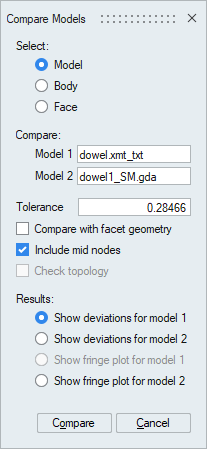
Dialog Box
This tool is used to identify the deviations in geometry between CAD-CAD, CAD-FEM and FEM-FEM. Deviations can be visualized using groups or fringe plot.
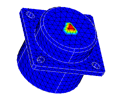
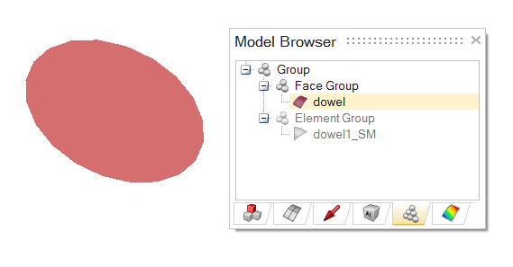
Deviations in CAD are created as a face group and the deviations in FEM are created as a elements groups. Deviations in FEM can also be visualized using fringe plot. Fringe plot display the deviations on each node. In case of higher order elements, deviations of mid-nodes can also be highlighted.
For Body and Face comparisons, the inputs must be from different models.
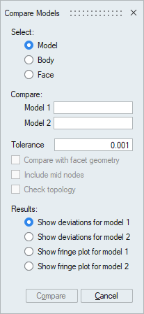
- Compare with facet geometry
In case of CAD-FEM comparison, this option is used to compare the FEM model with the facet geometry of CAD model. By default, FEM model is compared with original CAD geometry.
- Include mid nodes
In case of higher order FEM comparison, this option is used to identify the deviations in mid-modes.
- Check topology
In case of CAD-CAD comparison, this option is used to check the topology between the CAD entities.
Example
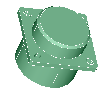
CAD - FEM Comparison
| CAD | FEM |
 |
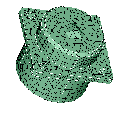 |
| Deviations in CAD | Deviations in FEM |
 |
 |
Fringe Plot display for FEM deviations