Prediction
![]()
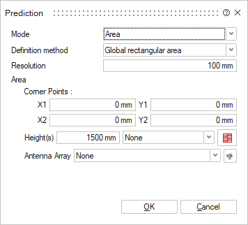
The prediction planes dialog allows the definition of either points, trajectories or a 2D plane where the results are to be computed when running the WinProp Solver.
Area Mode
- Definition methodTo define the area of the prediction plane, choose one of the following:
- Global rectangular area defines the plane by specifying the global X and Y coordinates.
- Individual areas for each transmitter adds a prediction plane with a specified radius around each antenna/transmitter in the model.
- Resolution
The Resolution defines the resolution with which the prediction is computed and the size of the result pixels used for display. Typical values for indoor scenarios range from 0.1 meters to 5 meters, with 1 meter being typical. The smaller the resolution, the higher the computation time.
- Corner points
Specify the X and Y coordinates of the 2D plane.
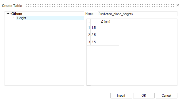
- HeightsThere are two options when specifying the Height(s):
- Single height: To specify a prediction plane at a single height, enter a value in the Height(s) field.
- Multiple heights: To define multiple heights, click the table
icon and import the height(s) (.csv,
.dat or .txt file)
or use the right-click context option when clicking on a row
number to insert a new row. Alternatively, an existing table can
be selected using the drop-down list.
- Antenna Array
If an antenna array is associated with the prediction plane, select the antenna array from the drop-down list.
Points Mode
This option defines prediction points where the results are computed when running the WinProp Solver.
- Resolution
The Resolution defines the resolution with which the prediction is computed and the size of the result pixels used for display.
- Points
To define points, click the table icon and import the points (.csv, .dat or .txt file) or use the right-click context option when clicking on a row number to insert a new row. Alternatively, an existing table can be selected using the drop-down list.
Trajectories Mode
- Trajectories
To define trajectories, click the table icon and import the trajectories (.csv, .dat or .txt file) or use the right-click context option when clicking on a row number to insert a new row. Alternatively, an existing table can be selected using the drop-down list.
- Sampling
Distance: The trajectory is sampled at the defined sampling resolution. If the distance between the defined trajectory points are larger than the specified distance between evaluation points, sampling points will be added.
Time: The trajectory is sampled at the defined time resolution.